Turning a Fox into a Snake

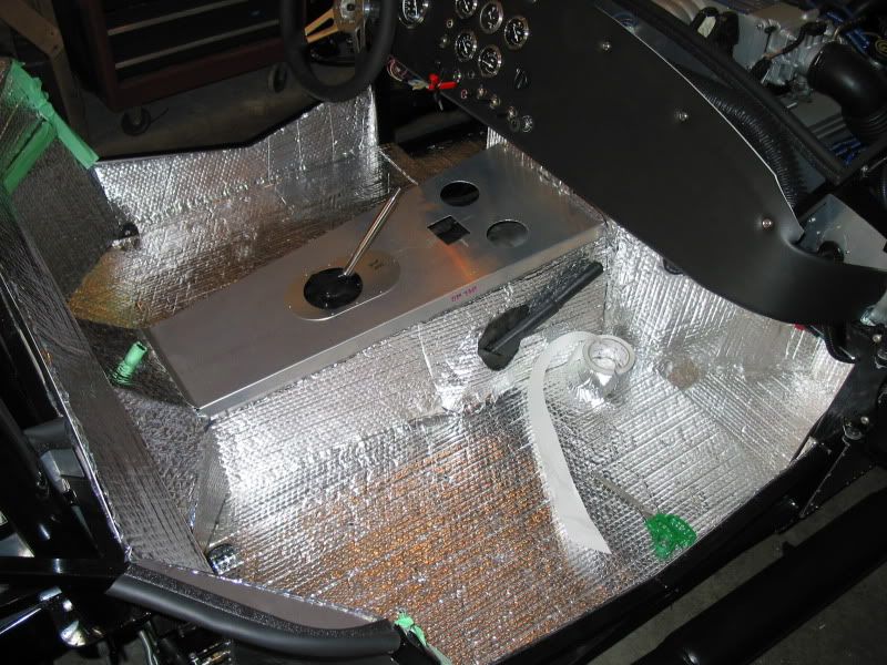
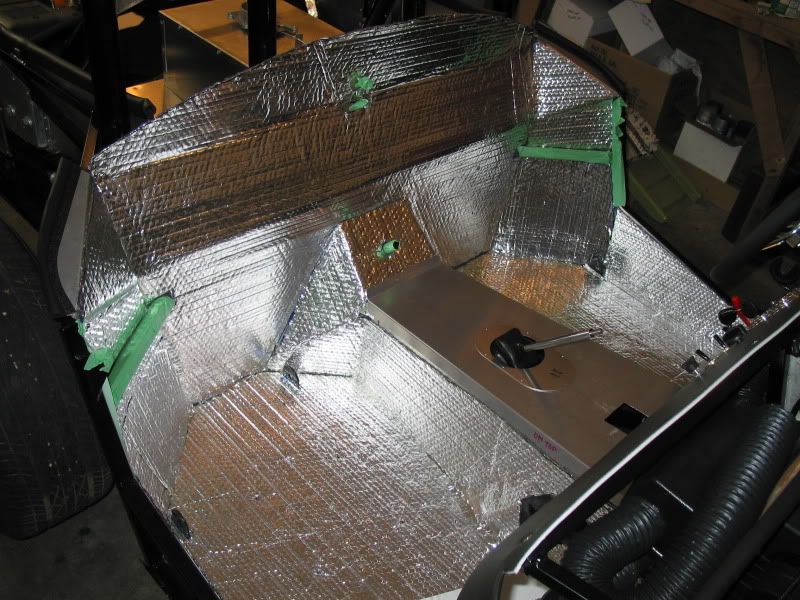
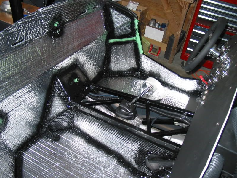
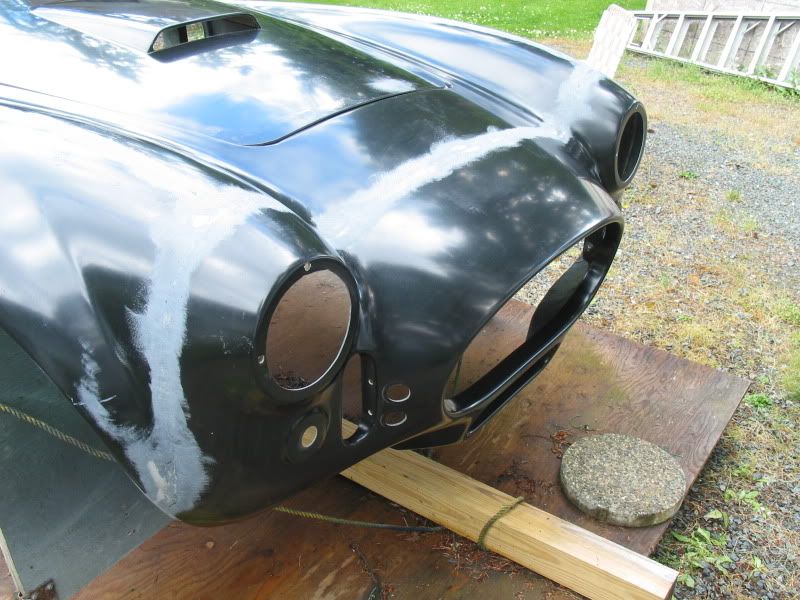
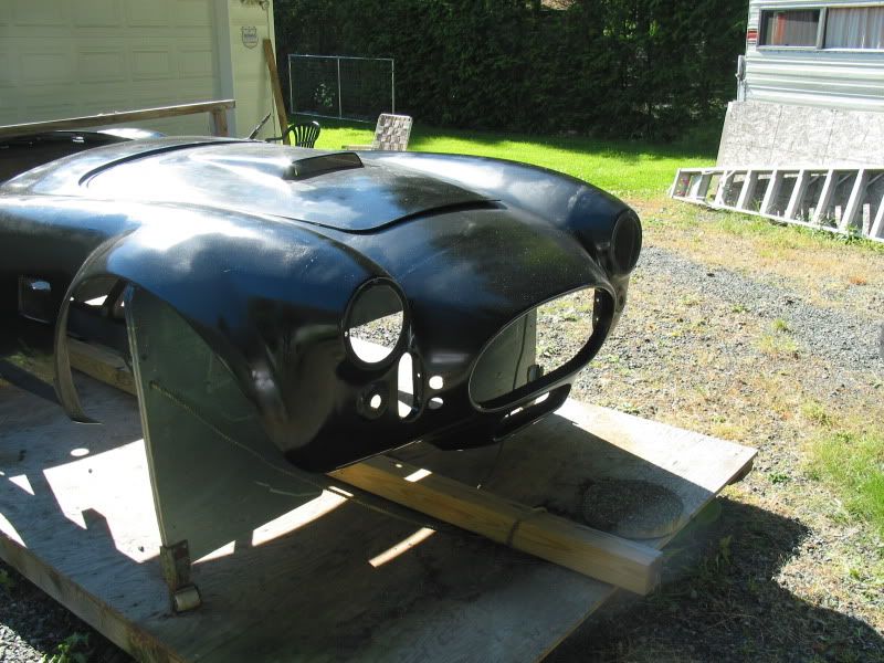
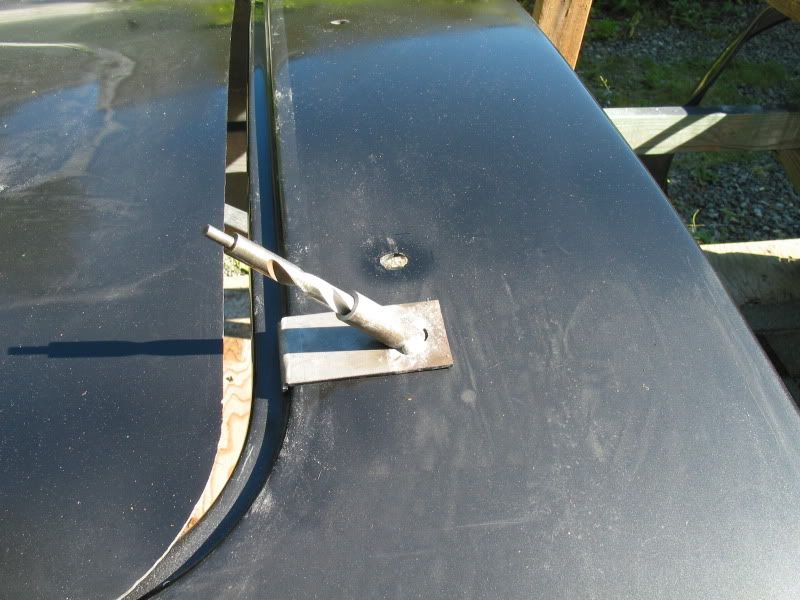
Good question.. the first few months after it's arrival, it went pretty slow, as it was so damn cold in the shop. I finally bought a 220v industrial heater, and it made a huge difference in how long I was able to work in the shop. Then there was the frustration of being stalled out on certain parts of the build, because of waiting for parts, that as much as I tried, I could not source in Canada. As mentioned, you can always fall back to drilling or riveting the cockpit panels, to pass the time while your waiting

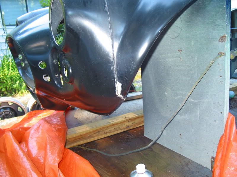
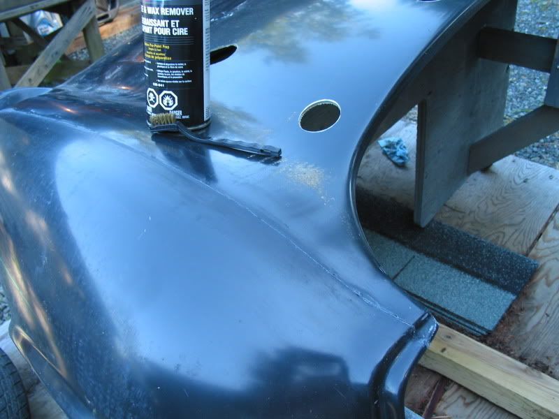
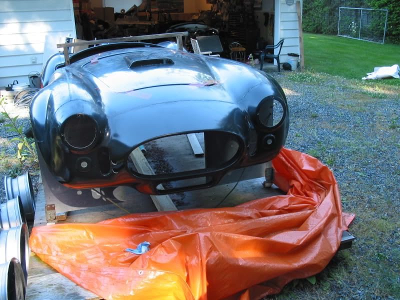
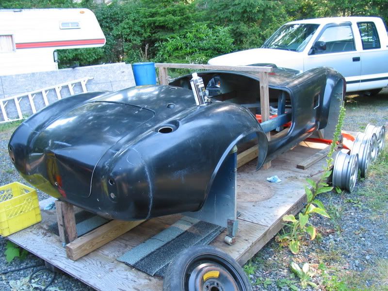
As to your original question. The crate arrived in February 2009, and I had it licensed for the road in Sept 2010, so about 18-19 months. The painting and final body work is underway, and could be three months, or longer, at the rate it's going. I guess if I was going to do the body and paint myself, as several builders have done, you could probably add hmmm...still maybe3- 4 months to the 18-19 months, I already worked on it.

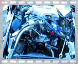
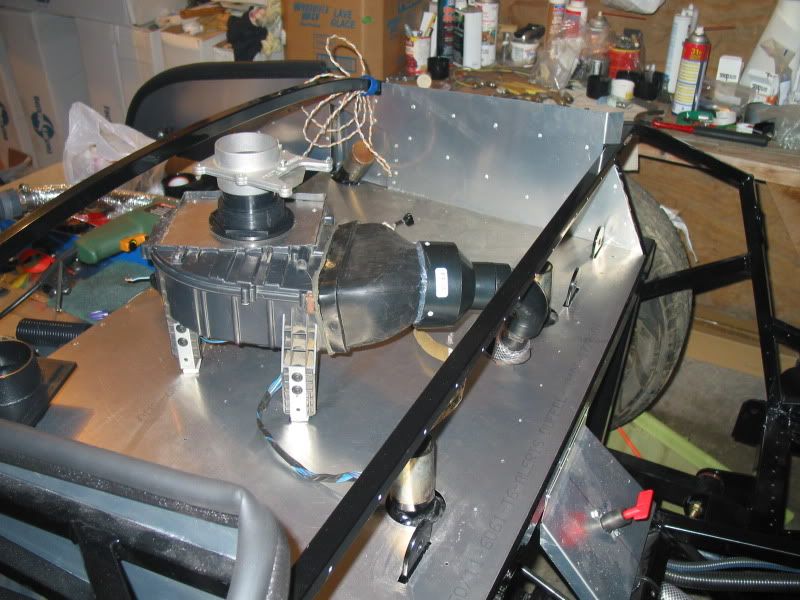
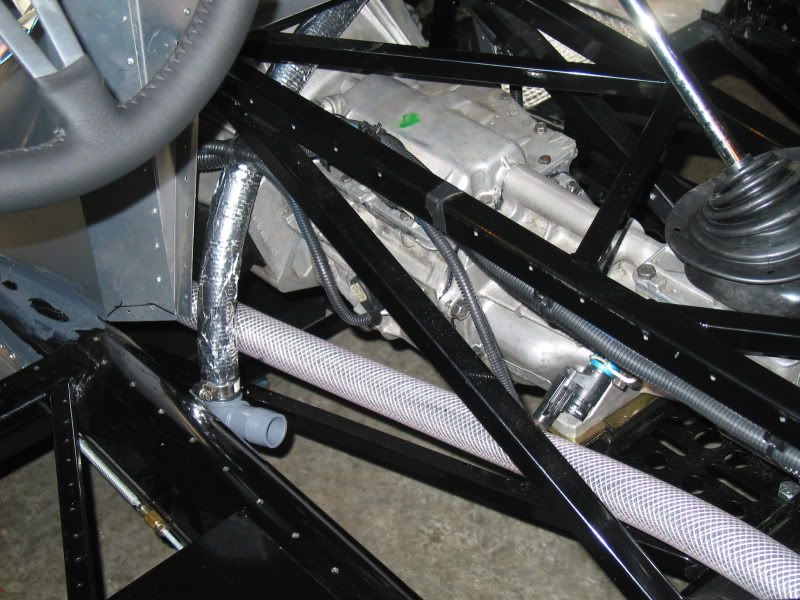
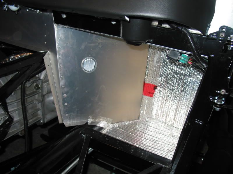
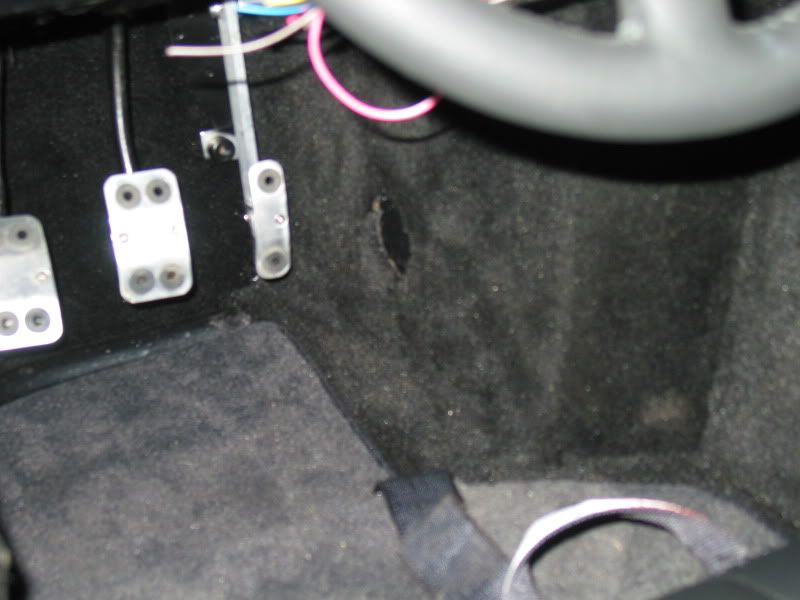
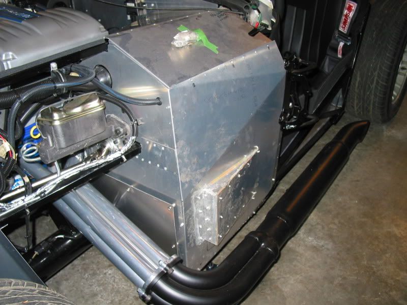
It really depends how committed you would be to finishing it, and how fussy you are during the build process. Any modifications to the basic build, such as the dead pedal footbox extension, footbox cooling system, etc.. take up time. Some fellows have done a basic build in as little as six months, and that's just evenings and weekends. Usually those builds don't include heaters, wipers, mounting tonneau covers, etc.., and is with new parts, not donor parts. Donor parts take extra time to clean, rebuild, paint, etc, vs pulling a new one out of a box, ready to bolt on.
 
FURTHER PROGRESS

So things are moving along fairly smooth on the build at this point, and since the engine install seem to have accelerated slightly..

The main concern I had at this point, is "Will the engine run?" I have never heard it run, although the wrecker assured me it was running fine when the GT was initially towed into his yard. He guaranteed the engine, even knowing that it may be some time before I was going to be ready to try it. Great, except I had spent a lot of time and money, regasketing, cleaning, and painting this engine. I really wanted it to work.

The weather didn't seem like it wanted to co-operate, with scattered rain showers the last few days. I didn't want to try starting the car in the shop. If there were coolant, oil, fuel leaks, or electrical shorts, or any other problems, I didn't want to sacrifice the shop..
Finally we got a break in the clouds, so we lowered the car down off the ramps, and jack stands, and rolled it outside. The first thing we had to do was to check for fuel line leaks, and electrical shorts. We hooked up my boats older battery, which I had charged for a few hours and made sure there was a large fire extinguisher on hand. I turned the key to the "on" position inti tally to run the fuel pump. The pump ran fine which was a relief, and there was no smoke from under the dash, or anywhere else. So far so good.!
After cycling the fuel pump a few times there were two spots on the fuel lines that gas was leaking. One was at the filter, where for some reason the clamp holding the rubber FI line on the Ford coupler, wasn't doing the job. We tried tightening it to no avail, so decided to simply replace the clamp. To do this we had to remove the hose, which as it turns out was extremely difficult. After cutting the hose to get it off the fuel filter coupler, and replacing it, and the new clamp, the leak stopped. A few more cycles of the pump showed another leak on the flared fitting on the supply line. The nut was a still able to be tightened up slightly, which stopped the problem. OK! we were good to go.

The engine cranked..and cranked again..hmmm what the heck? not even a pop? Ahhh.. my buddy Larry had pulled the coil cable off the distributer, as he felt it would be good to crank the engine over to build some oil pressure before it started..makes sense..He plugged it back on the cap, and we cranked it again..still nothing,, crap!

I pulled a plug, to see if we were getting spark, yup. What now? We had spark, and you could hear the compression in the side pipes as it was cranking. Only thing left would be fuel right? I thought, well maybe the regulator isn't working, or the fuel pump isn't getting the pressure up. I thought perhaps there was some air in the system as well, since the lines were all new. I pushed in the Shraeder valve, expecting air or fuel to come out. Nothing. Not even a drop of fuel. What the hell..

I dug out the Ford service manual, and read aloud the info on how the fuel system works for this engine. Larry followed the system as I read, and then said, "I think I figured out the problem, you have the feed line on the wrong fuel rail" Sure enough at the engine end I had mixed up the two rails and had the feed line on the return rail, and return on the feed line. The fuel was just dead ending at the pressure regulator..and couldn't reach the injectors of course..DOH! I hoped like heck the regulator wasn't wrecked, as sometimes the valve can be damaged from this kind of goof up.

Another short struggle ensued as we switched lines at the fuel rails. We tested the connections for leaks with another run up of the fuel pump. All good..ok let's try this again.
The engine barely cranked over before firing right up! YAHOOO! Man did that sound good to my ears. A huge relief.

We ran the engine up to temperature, and added coolant as the air purged from the cooling system. It idled nicely, and the few times I revved it up a tad, it sounded pretty strong.
I installed a 185* thermostat, so as temps rose it opened properly as could be seen on the gauge. As it has an electric fan, rather than the stock pulley driven one, temps climbed up further, to around 200*, at which point I set my electric fan control to turn on, then set it to turn off, when the temp. lowered to 190* . I'm really not 100% positive that these is the best settings. (If anyone can offer further insight on what they should be set at please let me know.)

It looked like all the gauges were working correctly. It took a long time for the oil temp to even register on the gauge, but after awhile the needle moved off the 140* mark just slightly. I had only put in perhaps two gallons of fuel for this trial run, but the fuel gauge was still registering slightly. The tach seemed to be working fine. The volt meter showed 12 volts on initial start up, but continued to drop down the longer we ran the car. My alternator charge light was glowing red, so I suspected that the alternator wasn't working..hmmm my wiring or the alternator itself? My neighbor came over as he could hear the car running, (loud but sweet). He is a mechanic by trade so he did some quick checks of the alternator connections with my multi-meter. All seemed good. he then touched a hacksaw blade to the back of the alternator to see if there was any magnetic field. Nope. He figured it was the alternator, or diode that may be bad. I have another alternator to try, thanks to HELI, a member here on the forums. Bonus! I hope this solves the problem.

The alternator from HELI is off his 93 Mustang Cobra. Can anyone confirm that this alternator is compatible with the harness from my 90 GT? The connectors appear to be the same, but I don't know if they are wired different internally.
Where alternators compatible between those years? I don't want to fry something.

The voltage finally ran down in the battery to about 8-9 volts, and the engine started running rough, I figured the fuel pump wasn't able to keep the pressure up, as well the ECM may have been struggling.
We shut it down, and rolled the car back into the shop.

I have a regular digital camera, not a video camera, but was able to capture the "First Start" moment briefly, as seen here. My buddy wasn't sure if the camera was even recording or not, as evident by his commentary. LOL

FIRST START
 
I mentioned previously that I was working on a footbox cooler system. I finally came up with a system, although rather unorthodox seems to work very well.

I had previously tried using a marine bilge blower, to push fresh air, through some flexible corrugated tubing, from the trunk area up to the footboxes. The combination of the reduction required to be able to use the tubing, (3" to 1-1/4" ID) and the fact that it was corrugated tubing, prevented any decent amount of air flow. Certainly not enough to warrant using it.

My friend donated a heater blower from a Mazda, that he was stripping to sell parts. I didn't need the heater core, so the blower itself from this smaller car was reasonably compact, and fairly self contained. This blower also has a four speed switch which is an added bonus, as there are times where more air flow may be needed then others. Sitting in traffic for example..Being it has a squirrel cage fan, it moves about ten times the air the bilge blower did. The only negative is that it is about three times the size of the bilge blower fan unit I had previously, so I will sacrifice some trunk space.

I mounted the blower in the centre of the upper trunk floor, and after doing some fabrication on both the air outlet, and intake, connected a smooth 1-1/4" ID hose to it. I ran this hose under the trunk floor, up along the tranny tunnel area to just behind the bellhousing. From that point we installed a T fitting, so I could run flexible hoses over to the passenger footbox, and another to the drivers footbox. The flexible hoses were insulated from tranny and engine heat, using a heat wrap tape. These and the main hose leading from the blower were all zip tied to different points on the frame to secure them firmly. An outlet vent was installed in each footbox to which we attached the insulated flex hoses.

The fresh air will be drawn in through a small scoop, that will be mounted on the body, between the roll bars,. I have decided to have the scoop opening facing backward. This may help prevent water from entering the trunk area, (if for some reason I ever get stuck in a downpour), as well I can control the air flow better. Air will not be forced into the opening from forward motion when mounted in this position, but rather drawn in via the blower, when wanted. To prevent "any" air flow when I don't want it, such as on a cool evening cruise, I will be installing a cable controlled blast gate.
To finish off the project I will fabricate an aluminum box to close in the sides and top of the blower, with allowance for the intake. This will give the trunk area a little cleaner look by hiding the unit.
I still have to decide where I am going to install the 4 speed switch. At this point for the ease of wiring, I think it may go on the rear cockpit bulkhead. This will be only for controlling the speeds, as I have already installed an on/off switch in the dash for it.
Here is a few pictures of the unit, as it was being installed. I tried it all before fastening anything down permanently, and it works great!

TRUNK MOUNTED BLOWER (blastgate visible on top of blower intake)
IMG_3006.jpg


Here you can see the hose leading up to the T fitting, and some of the insulated hose that leads to the passenger footbox.
IMG_3008.jpg

Passenger footbox outlet vent..
IMG_3007.jpg
 
ROLL BAR INSTALL

You need to pre-fit the roll bar, or in my case roll bars, as I decided to mount a optional passenger one as well. These are removed later of course to put the body on, but it is easier to do the measuring and drilling with the body off.

All the mounts of the roll bars are welded on to the frame from FFR, other than the passenger third leg mount. This is bolted down to the frame after the trunk floor aluminum is installed. It is only used if the RH roll bar is being installed, and comes with the optional RH roll bar,along with the needed bolts nuts, and washers.
You start by slipping the roll bars onto the frame mounts, then measure to make sure the tops of both bars are at the same height. You then drill holes through the bars, and through the mounts. The third leg also needs to be drilled where it attach's to the main hoop of the bars. My bars are powder-coated black, but optional chrome ones are also available. To help start the drilling I used a spring punch to mark the hole, then a smaller bit to do a pilot hole. The 5/16" bit was then run through. It's a bit of work drilling them, so use good sharp bits!

MOUNT AND BAR DRILLED
IMG_3011.jpg


ROLL BARS INSTALLED
IMG_3010.jpg


Cockpit aluminum work.

I started to work on the final installing of the cockpit aluminum panels.
You first need to pre-fit the panels, and drill them for the rivets. Some of the panels take a little tweaking, and even a bit of trimming to get them all in place nice and neat. (I did this all very early in the build, usually when I was waiting for a part to arrive, or if I only had an hour to work on the build, so I didn't need to do this at this point).
Prior to the riveting, you need to put a bead of silicone around all the frame, and adjoining aluminum panels. This prevents wind, and water leaks, and can reduce any potential for rattling, or vibrations.
There is an order of installation, which is evident the first time you pre-fit the panels, so it's a good idea if you mark the panels as to their orientation to others, and the frame at that time. I simply marked them with a felt pen, what was to go where. The carpet will eventually cover all my notes..

COCKPIT ALUMINUM
IMG_3012.jpg


The finishing touch on these panels is to go around with some seam sealer, and seal any gaps there may be, in corners etc.. You can also use aluminum tape on the inside to cover the gaps, which will also allow the seam sealer to have something to butt up against.

Almost ready for a go kart ride!
IMG_3015.jpg
 
[h=2]Build continues,[/h]
A couple more productive days...

For the first start, and run up to temparature, I had used 3.5 liters of oil, and 1.5 liters of ATF mixed. This was to do some internal cleaning of the engine of varnish build up, etc.. Some people have used 100% ATF for this process, but I was a little hesitant. One fellow who did this had so many contaminants that it plugged his oil filter almost immediately, which then went into the bypass mode. The contaminants then plugged his oil pump pick up screen, and starved engine, which quickly destroyed his crank bearings..not a scenario I wanted to happen..

I wanted to warm the car again before draining the oil/ATF mix, but first had to replace the bad alternator. I had confirmed that the 93 Mustang Cobra alternator HELI had sent me, would work with my year harness etc., so after switching the fan, and pulley back over to it, I had it installed pretty quickly. It worked fine, and my charging light went out and the volt meter was reading a steady 14.5 volts
That was a relief, I was worried that I had screwed up some wiring, or perhaps had installed the resistor incorrectly.

The old battery I was using from my boat, for the initial start up, was drained quite bad, and I was warned not to use a poorly charged battery or it may harm the alternator. I needed a smaller size battery anyway as it had to fit in the trunk, so with measurements in hand I went shopping for a battery. I checked Wal-Mart, which had a good selection, and decent prices, although some of their stock of the size I needed was slightly dated, (probably due to it's uncommon size for modern cars). I also checked Costco, great prices, and although they had the size I needed, the -/+ post positions were opposite from what I required for my cable set up.. I finally picked one up at Lordco which had the size, and post position I needed.

After warming up the engine, I then drained the oil. Considering what little run time it had, it was pretty dirty looking, so I think the ATF did a decent job of cleaning.

Now here's an odd thing. After I changed out the oil filter, I added a bottle of 10-30 Mobil 1, on which the jug clearly stated 5 litres. After another start up, and letting it run for awhile, I shut it down, left it for 5 mins, checking for leaks and such. Upon checking the oil level I was way over the full mark on the dipstick. The specs for the 5.0 called for 5 litres of oil capacity, including a new filter..I pulled both drain plugs on the pan, so it was clearly empty.
confused.gif


How much was in the bottle? Maybe closer to 6 litres then 5. Bloody odd considering the price of oil these days, for a company to overfill a jug by that much..
So now I have to drain off some oil or risk blowing a seal, etc..I think I'll suck it out of the dipstick using the oil change pump I have for the boat, rather than pulling a pan plug. Easier to control the amount I remove this way. Pain in the butt..

I was thinking of putting some carpeting on the trunk floor, so while I was in town, I checked to see if I could find carpet that would be suitable. Didn't have any luck, either they were way to large a roll, or the wrong color/material for what I wanted. I found out later that Crappy Tire sells automotive type carpeting, suitable for this, so I will check this out in the next few days.

I spent today doing the final install, on the trunk mounted footbox blower, it's wiring, and making a custom mount for the switch. I have the 4 speed switch coming out between the seats on the rear cockpit bulkhead.
I also did some work on the blastgate mounting set up. I still have to purchase a push/pull cable to control it, and rig up a mount for the cable anchor on the blastgate. The cable control knob will be just above the fan switch. I'll post pictures of that area, when it is all finished.​
 
BLOWER BOX FINISHED

I picked up the aluminum to fashion a box to hide the foot box cooling blower a few days ago, so yesterday was spent building and installing it.
My friend Larry worked in the sheet metal trade several years back, so he volunteered to cut and bend the aluminum to the specs I had drafted up for it. He used two pieces of angle iron in a vice to act as a metal brake to get the 90* bends for the top and end piece. We did some careful measuring to get the hole for the blastgate in the correct position, then used a 2" bi-metal hole saw to cut the starting hole. Larry then carefully cut the hole to the needed size, with tin snips, and filed it to finish.
It tidys up the trunk tremendously, as can be compared to the earlier picture posted showing the fan blower initial installation.
It turned out great, in my opinion, and was really pleased with the end results.

In this picture you can see the switch mounting plate, which was fabricated to allow the fan speed control switch to be activated from inside the cockpit. This plate will also act as a support for the blastgate control cable to be mounted to. The relay is also visible to the right of the switch mounting plate, which was needed for the heavier amperage draw of the blower fan.
IMG_3016.jpg

Switch from cockpit side. (You can also see in this picture the brush on seam sealer used on the cockpit side to seal up the aluminum panels where needed).
IMG_3017.jpg

The finished box with air intake blasgate installed
IMG_3018.jpg

Blower box finished, the finished blower wire harness is also visible.
IMG_3019.jpg


I will be looking for a blast-gate control cable today. I think a simple choke type one should work, cut to size. I'm also going to see if the local Crappy Tire has stock on some carpeting so I can finish the trunk floor.
 
Some of the things I have done, such as the deadpedal mod, or this last info on the footbox cooling blower, are not standard in the building of these cars.They are personal choice modifications. Hopefully it does show to perspective builders, or interested readers, that you do have choices in how you may personalise these vehicles. Some builders want to build them as rapidly as possible, and pretty well do a "stick to the book build", some build them with re-sale value in mind. adding expensive upgrades and features. Others build them with trying to gain the ultimate in performance.

Budget considerations can also play a huge role on what builders may choose to do. For instance there is one Island builder who has invested, an estimated $100,000 on his FFR Roadster. I haven't seen his car yet, but apparently it is spectacular. Keep in mind that things can be changed or added as one can afford it, so if you dream of something you want on your build, you can always do it later.
smile.gif


Build Continues...

I went shopping for a pull cable for controlling the blastgate on the trunk blower. Lordco had a Papco one that looked good, but I was surprised at the price of $23 (with my car club discount). I had to stop in at Crappy Tire to see if they had any automotive type carpeting for my trunk floor, so I looked at what they had for cables. Glad I did. I actually got a Papco brand from them, but this cable had the added advantage of having all the other hardware I needed, as well, and all for only $14 at retail price. Me thinks Lordco are over charging for some things..

So anyway.. I drilled a hole in the rear cockpit bulkhead, for the control knob, and ran the entire length of cable through it (7'), as I had to determine the correct length to cut it off. I had to figure out how much movement was required to fully open, and close the blastgate. This done I pulled the inner cable out of it's housing, and cut the housing to length. Then I slid the inner back into the housing and cut it off at the proper length.
The control knob is simple to mount as it was originally intended for dash mounting, and uses a nut from behind to hold it firmly. You also need something to keep the cable housing end solid, so the inner cable can be pulled/pushed. A simple bracket was rigged for that purpose from a piece of aluminum. To fasten the end of the cable to the blastgate door, I used the small brass piece (that came with the cable set), after drilling a hole in the door. It all worked very good, and I was pleased with the end results.
Here is a picture of the finished product.
IMG_3020.jpg


Control knob.
IMG_3021.jpg


I also found some carpeting that was perfect for the trunk. It's almost identical to the interior carpet. A 6' roll by 36" was $19. (Other carpeting I had looked at began at around $5 per foot, and wasn't really automotive carpeting). This stuff is supposed to be resistant to water and staining, which can be a bonus if I ever get stuck in a real downpour.

I am torn as to whether I should now finish the interior, installing the rest of the insulation, carpeting, and padded vinyl shifter console. I would love to get this finished at this point, as everything is so accessible, but I hesitate as I worry about all the dust that may settle on it (and in it) when it comes to the body and paint work.
If I install it all now, I could do the interior masking myself, which may also cut down on the cost overall. This would help assure that it is done properly, and not left up to some apprentice.
If I leave it all out for now, it would mean having to take the body back off after painting to install it, so I worry about scratching the fresh paint..

Another choice would be to attempt to do the majority of bodywork myself with the body off the frame. It would mean that I would probably have to take the body on and off a few times, to ensure the fitting of the doors, hood, and trunk lid, but at least it would keep the dust down, as I could do all this outside the shop. Then I could take it to the shop just for the final prep work, primer and paint. Never having done body work before, I hesitate, as I don't want to screw something up, that makes it harder for the painter to correct later..
Decisions, decisions...

The next job is drilling the holes in the frame/cockpit floor, for mounting the seats, so this will give me some time to mull it all over..
 
Thanks ! That's great that you enjoy it. It took a lot of time back when I originally wrote it. I tried to keep it interesting, not get too technical, and throw a little humor in when I could.

Of course there were some questions and comments made here and there, by MC members, during the original post, so I have edited a few spots, but hopefully didn't leave out anything of pertinence.

BUILD CONTINUES

I had to take a few days off from the build, as I managed to slice my hand.
While climbing into the drivers seat, to get it in the best position before drilling the mounting holes, I brushed the rear cockpit bulkhead aluminum, with the back of my hand. Ouch..
Anyways being in a small town, with no hospital, I went to the local health clinic, to see if I needed stitches, and or a tetanus shot..crap they closed early..I went to the local pharmacy, and bought some special strips used to close up a wound, sort of like butterfly bandages. So far so good! I hope I don't get lock-jaw..
mouth.gif


Being that climbing in and out of the car is a bit of a feat at the best of times, and having a wounded hand, I opted not to work further on the seat mounting, but instead do some checking on my headlight and tailight wiring.

A simple 12V test light, showed that the reverse lights, and the license plate lights worked ok. Brake lights were good, as was the wiring for the rear lights in the running light mode. I didn't have enough resistance from the test light to get the turn signal relay to function correctly, so I used one of the t/signal lights (included in the kit), for testing.
Great, turn signals worked fine as well, so I moved on to the front of the car.
Headlight and turn signals worked fine there, but I couldn't get the running light mode to function. Hmmm. Where to start. I know the ground is good otherwise the other light functions wouldn't have worked. I also knew the headlight switch was ok, as the rear running lights worked fine in that mode. I was really concerned that the flaw was in the harness itself, which is all nicely wrapped in loom cover and fastened to the frame..The front harness is connected to the main harness using one of the Mustang OEM harness connectors, so I decided that was the fiirst place to start. If I was getting power to that point, then I could at least narrow down the fault to the shorter front harness. Test light soon confirmed I was getting power to the connector.
I studied the connector, and realised that the male pin, for the running light, didn't correspond with the female, on the other half of the connector. Hmmm.. a simple mistake by the supplier who did my wire harness diet. Not bad really, considering the huge amount of finicky work that is involved in this process.
It was easily remedied, once I figured out how to remove the pin from the connector. I found a good web site describing how to do the Ford, and other connectors, which made it simple to correct.

Reusing Plastic Wire Connectors

After correcting the pin location, another test revealed that all was good.. a thankfully simple solution, considering what I may have had to deal with..

The headlight, front marker and tailights are to be connected to the chassis harness with Weatherpak connectors, which from what I understand are the best for trouble free wiring. The Weatherpak connectors are supposed to resist corrosion, and make a good solid connection.

Weather Pack Terminals Seals Connectors Splices | Weatherpack | Sealed Electrical Connection | Weather Pack – Components and Tools | Weather Pack System

I gathered up all the lights, and spliced the pins for these connectors on to them. I used a drop of solder as well to ensure good contact.
The headlight and front t/signals have there own individual connectors, which are a different style, so they can't be mixed up with one another. Installing the pins into the male connector was simple enough, although I needed to make darn sure the pins lined up correctly with the female side of the connectors.
As there is two tailights per side, I can't actually install the connectors yet, as both lights need to share the ground and running light pins, on the chassis connector. (There is only one female chassis connector per side) I will need to splice these togeather after the body is on the chassis, as the tailight wires must pass through their individual holes on the body.

NOTE-Dialectric grease is recommended to be used on all harness connections, so it's good to have a tube of it handy. It further reduces the chance of corrosion, as well makes connectors come apart easier, even years later.
My Dad used to use Vaseline, which seemed to work good for his old cars, but I'm not sure if it is suitable with the newer vehicles..and forget using KY..
smile.gif


SEAT MOUNTING

My hand is healing up very well, no sign of infection etc, so yesterday I decided to tackle the job of mounting the seats.

Due to my height (6'-2") I opted to mount my seats directly to the floor. FFR does offer optional seat tracks, that can be used if you want the seat to be adjustable. Some builders use these, especially if their going to allow their wives/girlfriends, or perhaps a buddy to drive the car from time to time. I actually ordered one for the drivers seat, but opted out of using it after reading comments from other taller builders, on the builders forum. Direct floor mounting gives me the most leg room, and comfortable seating position. The passenger seat really doesn't need tracks, as far as I am concerned, as it's not like they need to reach pedals, or steering wheel.

NOTE-You need to this part of the job, before you insulate and carpet the floor. The reason for this will become evident.

The process is relatively simple. The bucket seats supplied with the kit, have the seat bottom held in place with Velcro. You can swing the seat cushion up out of the way, and actually look down at the seat framing, and the floor below it. The trick is to position the seat frame over areas of the floor that have frame members underneath it, for solid mounting. Remember the floor pan itself is simply aluminum, so you can't risk mounting the seats directly to it. They could possibly tear out if you were involved in a collision, or perhaps even some spirited driving, such as in slalom racing.
As the floor has been riveted to the frame at this point, you can use the lines of rivets to use as a guide as to where there are frame structures under the floorboard. FFR also has welded in two 1/4" thick steel plates, for added floor strength, as well as a solid mounting point for the Simpson 5-point harness's anti-submarine belt. These plates can also be incorporated in seat mounting. Trouble is you can't see these plates under the floor panel, so you need to do a bit of measuring, and transfer and mark the position of the plates, onto the floor top, so you know where they are. These reference points for frame members and plates are why you don't want to carpet the floor beforehand!

Because of the angle of the transmission tunnel, foot pedal position, and having to allow for the thickness of cockpit insulation, and carpeting around the seat, you must take all of this into account before actually drilling the mounting holes. It does take a bit of adjusting to get it all correct, and still have the seat framing lined up over floor framing. Once I had this this all set, using a Sharpie, I marked on the floor the outline of the seat framing. This was to make sure they were still set in the proper position when drilling. I drilled through the seat frame, and down into the floor members. After the first hole, I set a bolt in place, as I didn't want the seat shifting around as I drilled the other three holes. I did this each time I drilled a hole.
NOTE- The seat belt mounting tabs which protrude through the floor, as they are welded to the framing underneath, need to be taken into account as well, in seat positioning. This is to prevent having a belt mounting bolt, sticking into your seat. I got lucky on the first seat I installed, as I didn't think of this initially. Thankfully there was room for the bolt, or I may have had to cut a hole in the side of the seat material to allow for this...or reposition the seat, and drill new holes. Getting lucky is good at times like this..

Here is a few pictures to give you an idea of this job.
This first picture shows the rivets, and the steel plate markings, used to indicate where the frame mounting points under the floor are located.
IMG_3023.jpg

This image shows the seat bottom pulled up, so you can see the seat framing that needs to be drilled through, and bolted to the floor.
IMG_3022.jpg


Now that is all finished, I can move on to completing the insulation, and carpeting, (which I finally decided to do at this point in the build, rather than later).
 
COCKPIT INSULATION

Two reasons why builders do this. One is for heat protection from the engine compartment and headers. The cockpit aluminum can conduct heat quite easily, and as these cars are basically "fair weather" vehicles, much of the time is spent driving them on warmer days.
The second reason is to dampen the road noise, and give a more "solid" feel to the vehicle as well. If any of you have taken carpeting and insulation out of your car and gone for a spin, you will know what I mean. It has a echo/hollow sound. Bits of gravel, dirt, etc., kicked up from the tires will also be less irritating, as it bounces off the floorboards, and footbox aluminum.

Before I could install the insulation, I had to make a inner boot for the e-brake.
FFR includes a nice outer boot, but I was afraid that with the size of the opening for the e-brake handle, the outer boot would be a "catch all" for road debris, dirt, dust, and God forbid ,water, should I get stuck in a downpour someday..I also didn't want it to become a winter home for mice, during the winter layup..
I fashioned the inner cover using a piece of tire tube, which has the flexibility needed, and is tough enough that it wont rip. I cut it to the general shape of the opening, then used rubber cement, to stick it to the side of the tranny tunnel aluminum, where the e-brake handle is positioned. It looks like it will do the trick.

Many of the pieces of insulation I was able to cut to shape, using the supplied carpeting for a pattern. This sped up the job considerably, and I was able to get the entire cockpit done in a day.
I used the 3M #90 spray adhesive, (the same stuff I used for my dashboard cover material), to glue it directly to the aluminum. I first vacuumed, and then wiped down all the aluminum to remove any dust or debris left from drilling rivet holes. Then I prefit the insulation, and did any final trimming that was required ,so the seams would line up as best as possible. I used scissors to cut the material, as I found it cut a cleaner edge than a razor knife did.

INSULATION INSTALLED
IMG_3024.jpg


In some areas that I didn't want over-spray from the adhesive, I masked off. Where there were openings needed in the insulation for things such as my battery master switch, and foot box fan switches, I simply laid the insulation in place the marked where I needed to cut holes. For the seat mounting holes, I heated up a nail, (while holding it in a pair of vice grips), with my little propane torch, and simply melted a hole through the insulation material. It makes for a nice clean hole. I still need to cut out the holes in the rear bulkhead for the shoulder belts to feed through. For that I will use a razor knife.
I used some aluminum tape over some seams, as added insurance, or where there may have been a slight gap. A trick I learned on the builders forums, is to spray the insulation with some flat black paint in all the corners, and seams where the carpeting will be joined togeather. This prevents any "shine through" in spots that there may be small gaps in the carpeting. A darn good tip.

READY FOR CARPETING
IMG_3025.jpg


I left it all overnight to dry, although the 3M adhesive seems to set up fairly quickly.
Now comes the interesting job of carpeting the cockpit. As mentioned FFR includes the carpeting, and it is pre-cut to fit, although some final trimming may be required. It would be nice if there was one or two large pre-molded sections of carpet, but I guess that would add to the cost, and packing/shipping difficulties. Instead you get a box of all these separate pieces, that you need to put together like a jig-saw puzzle. To make things worse, the instructions on carpeting in the manual are basically non-existent. The one small picture they have of the carpet pieces is not showing exactly where they go..
frown.gif


CARPET JIGSAW PUZZLE
IMG_3026.jpg


So figuring all this out will be my project for the next day or so..
 
I decided to use a worthwhile tip I learned from the builders forum, regarding the areas that the carpet panels will butt togeather. Apparently there is the possibility of a slight gap in some spots, which would allow the foil backed insulation to show through. To give the interior a better look, it was suggested that all these seam areas be given a coat of flat black paint, so they are far less obvious. Makes sense to me. I still haven't quite figured out where all these carpet pieces joint to one another, but I had an idea, so I went over these spots with some black paint. I sprayed around the footbox blower vents, as well as the blower switch, and cable pull. Also the battery cut-off switch. Openings in the carpet will need to be cut in these spots, and I don't want the insualtion showing through here either. I also did around the ebrake handle, although after, I realised there is a boot going over it, so that was a waste of my time..

CARPET SEAM PREP.
IMG_3030.jpg


Now was also the time to add the Dynaliner product to the footbox floor. Some simple measurements and a bit of trimming, and I had the pieces all cut. This product has a self adhesive backing, so it was very easy to install. I just had to make sure it was lined up properly first.
My idea was that by using this product in the "high use" areas, it may prevent the carpet from slipping, better than if the carpet was applied directly to the insulation. I suspect the carpet may adhere better to it as well, although only time will tell if that is the case or not..

DYNALINER INSTALLED
IMG_3031.jpg


While I was waiting for the black paint to dry, I decided to apply the foil backed heat insulation material to the underside of my tranny tunnel.

I also decided to apply the padding that was going to go under the the vinyl cover I had planned for the tunnel cover. I was given a product to try (free), from a local flooring store that I went to, as the local upholstery shops didn't have anything appropriate. This padding was actually meant to be used as a laminate floor underlay but it looked like it would work, and the price was right! I wanted some padding under the vinyl to make it more comfortable to rest ones elbow on whiule driving, but also hoped it would hide the rivet heads used to hold the shifter filler plate in place. This filler plate is supplied in the kit, to allow a builder to adjust the shifter lever opening to suit his particular tranny. It centers the shift hole the boot and trim ring will eventually hide. (You can see it in the one picture I posted previously on insulating the cockpit)

I trimmed a piece out, after some careful measuring, and then using a spray adhesive, I rolled it down smooth over the tranny cover aluminum. On the sides pieces that drop down, I used clamps and paint stir sticks to hold it in place, while the adhesive dried. (The stir sticks prevent compression marks on the material, from the clamps) I let it dry overnight before unclamping, and it seemed to have adhered very well. I pray that the heat from the sun on hot summer days, won't cause the product to lift, or get air pockets in it.
In this picture you can see all the clamps I used at the sides, as well as the insulation applied to it's underside.

TRANNY COVER PADDING AND INSULATION
IMG_3029.jpg


Here is a top view after the padding was installed, and prior to the vinyl cover being applied.

TRANNY COVER
IMG_3032.jpg


I may decide to apply some edging material to the sides of the cover where it drops down and meets the tranny tunnel side carpet. Just not sure how that will look..perhaps too refined for an old school race car?

I will begin the..(interesting?)...job of installing the carpet pieces today. I hope I don't mess it up, as I think once the adhesive is applied you only get one shot at it..
 
Had a bit of a disappointment yesterday..Oh well, live and learn..
rolleyes.gif


I measured and cut the vinyl for the tranny cover. Sprayed the underpadding and vinyl with adhesive. Carefully laid the vinyl in place, and then using a small paint roller, smoothed down the vinyl. I hoped it would turn out as nice as the dash did.

I set it aside to do some work on the cockpit carpeting, and then checked it again about twenty minutes later. Crap.. there were air pockets forming under the vinyl. I re-rolled it down, but ten minutes later they appeared again..hmm what to do now..?
I decided to peel the vinyl back off, while I still could, and discovered that the padding underneath was full of fissures..I gather that it reacted to the adhesive. I guess it was gassing off or some chemical reaction was taking place. I had used a Permatex brand adhesive that I thought I would give a try, as it had listed on the can that it was for automotive upholstery, headliners, foam, etc..There was a warning though, that it may react with certain plastics. I guess the underpadding was one of them..PMO.. As mentioned previously, this "free" padding material I used was made for using as an underlay for laminate floors, and I gather was not designed to be used with an adhesive..I guess you get what you pay for..in this case, nothing..
rolleyes.gif
Odd why it didn't react when I glued it to the cover, but I was using the 3M #90 spray adhesive for that..

So now it looks like rather than trying to strip this padding off, buying new padding and vinyl, another $35 can of the 3M #90 and starting all over, I will simple use the original carpet for the tranny tunnel cover. The carpet will not allow the fissures to show through, as they are very small. I'll use black silicone to adhere the carpeting to it, instead of the Permatex product.

The carpet may work out better in the long run, (as reminded by another builder), that the vinyl cover can get very hot after sitting in the sun, and could be hard on the arms. elbows..
[h=2]Build continues..[/h]
COCKPIT CARPETING

I started in on carpeting the cockpit, and although a little careful trimming of the supplied pre-cut pieces was required, they actually fit very well.
I started on the rear cockpit wall, as per the instructions. I used black silicone as adhesive, as it gives a little time to work the carpeting before it sets up. After it dryed I put the shoulder harness's in place.

REAR COCKPIT CARPETING

IMG_3033.jpg


I then carpeted the front foot boxes on both sides. It was a little tricky trying to make sure that the hole for the foot box vent outlet, was in the correct spot, but I managed ok.
The carpet for the center console I had to cut into three pieces, so I could still keep the top cover removable. I first glued the carpet to the top cover, and the cut out the holes for the shifter, ashtray, and cup holders.
The console side carpeting on the passenger side, needed a hole cut in it in the exact spot for the ebrake handle to slip through. A little tricky, but it ended up right where I needed it. I then glued in the passenger side carpet that goes on the side of the tranny console.

I was concerned that where the side carpet meets the top cover carpet, there would be an ugly seam. I decided to make a seam cover for that spot. I used a piece of aluminum (tile edging), and covered it in vinyl, after drilling some holes through it. I also drilled and tapped the tranny frame to accept 8-32 phillips screws.
I put the top cover in place, then attached this seam cover, using stainless steel screws and trim finishing washers. It does a good job of hiding this adjoining seam, and looks pretty good as well. You can see it running horizontaly, above the e-brake boot.

E-BRAKE BOOT AND SEAM COVER INSTALLED

IMG_3039.jpg


The e-brake boot was hell to put on! I gather the seamstress who sewed in the elastic gather that slips over the e-brake handle, measured it incorrectlly. I tried pulling it over, nope. Pulled harder still, nope.. I was really sweating hard by the time I finally got it slipped over. I used silicone spray lubricant, and a spark plug socket, that I jammed into the gather, which I then aligned over the handle, and using both hands gave the boot a major tug. It slipped off the socket, and on to the handle, without tearing, thankfully..I'd like to give that seamstress a piece of my mind. grrrrr..

Anyhoo, with that done, I was able to place the passenger floor carpeting in, which is the last piece to be laid. As I was also using the optional FFR floor mat, over the floor carpeting, I realised that I would need to add a hole through it as well, for the anti-submarine belt mounting bolt to fit through. I had already melted holes through the floor carpet for the seat mount bolts. A nail held in a pair of vice grips, heated up with a small torch, works great for making these holes. It burns clean through, and seals the hole so the carpet won't fray in these spots. Don't breathe the fumes..gag..

I then bolted in the anti-sub belt, then the lap belts, and stuck the seat in to see how it all looked..I'm happy! I still need to adjust the overall shoulder harness belt length before permanently mounting these, but I needed a person to actually sit in the seat first. The Simpson belts have adjusters that can be used once a person is seated, but they also added a lot of extra belting to allow for the different vehicles they may be used on. That is what I still need to adjust.
Although it's not required, I liked the look of bezels surrounding the holes where the shoulder harness's emerge from the rear cockpit bulkhead, through the carpet. There are some available from retailers, but I got lucky when a fellow builder in North Vancouver decided to have a friend make him some out of stainless steel. He asked if I wanted any while his where being made. The price was a 1/4 of what they would be otherwise, so I jumped on it. (I also had bezels for the steering column, roll bars, and window frame to body, done at the same time..)
First I drilled through the carpet, and into the framing behind. I then tapped the holes to suit the 8-32 stainless steel cap head screws I was using, to hold the bezels in place. Both the drilling and the tapping was made more awkward with the carpet in place, as the carpet fibres kept wrapping around the bit, and tap..I should have done this before hand..well live and learn..lol
You can just see the bezels in this picture..

SEAT BELT HARNESS INSTALLED

IMG_3046.jpg


PASSENGER SIDE INTERIOR

IMG_3041.jpg


Now on to the drivers side, which should be much easier as I don't have to worry about an e-brake handle..
I discovered that the supplied seat mounting bolts are to short now that I have the insulation and carpeting in place. I gather FFR only takes into account the thickness of the carpet, as insulation is optional. I guess another visit to the hardware store is required...​
 
A few more things accomplished..

First I finished up installing the shifter boot. I used contact cement under the chrome shifter bezel to adhere the base of the boot to it. I also used some of the dynaliner between the bezel and the tranny carpeting, to sort of pinch the bottom of the boot under the bezel. I hope this will help prevent the boot from eventually pulling out from under the bezel. Only four screws would hold the bezel to the tranny cover otherwise. With the supplied rubber boot this would not be a problem, but the soft boot could possibly tear away from the screws, without these added measures. (oops..sorry it's a little blurry)
SHIFT BOOT INSTALLED
IMG_3051.jpg


I mentioned my pedal issues in my last post. What I ended up doing was to cut the gas pedal in half, so it is much slimmer, (similar to what regular cars have). I used a cut off wheel on my angle grinder, then cleaned up the cut edge with my bench grinder and wire wheel. It turned out looking pretty good. I found that by doing this, it now prevents the problem of stepping on the gas at the same time I hit the brake.

Because of my long legs I find I can't really sit straight legged and that when I am sitting in the car my right leg is resting on a bit of an angle, down to the pedals. It's actually pretty comfortable, but the problem was that I tend to use the edge of my shoe to depress the gas pedal. When going to wide open throttle, I was just barely reaching the pedal with the tip of my shoe, so I lowered the pedal slightly on the pedal arm and that allows me more "grip" on the pedal with my shoe. Feels great now.
PEDALS
IMG_3052.jpg


I hesitated to do the trunk carpeting at this time, but realized how awkward it would be trying to do this after the body is on. Reaching up into the front of the trunk area, would be a real pain. First I sprayed some black paint on the areas where the carpet seams would be, so the aluminum wouldn't show through, if my carpet cutting was off a tad. For the upper trunk floor area, I decided to use black silicone to adhere the carpet to the aluminum. For the lower trunk floor, as I previously mentioned, I am using the self adhesive Velcro strips. One side on the carpet, the other on the floor.

I took the roll bars off to make this carpeting job simpler, and as they also needed to come off for the body to go on. I Had to use a rubber hammer to "ease" them off their mounts, as they really fit tight..
TRUNK CARPETING
IMG_3054.jpg


As the pedal adjustment issue was done, I decided to attach the drivers side outer footbox panel. I am not going to add silicone seal at this time, and will use self tapping screws rather, than rivets to hold it in place. This is in case I need to remove this panel later to adjust the drivers dead pedal extension that I added. I have some concerns it may interfere with the body if I extended it to far, but I can't really tell until the body is first fitted... I will seal and rivet this panel the next time the body comes off, if all fits well and doesn't require adjustment. The upper engine side, footbox cover I designed to be removable, so I can access the clutch cable quadrant, and some electrical wiring. (That panel is not visible in this picture).
IMG_3053.jpg


I am hoping the next pictures you see will be with the body on for fitting..I'll keep my fingers crossed..
biggrin.gif
I got a kick out of this comment from Dan (MC member), who was reading this build thread, so I will include it here.

"Again, very nice work, this is by far the most complete build this site has ever seen. Pardon the pun, but I've been riveted to this thread...if I didn't have to sleep I'd love to build on of these.
The seats look great, and the harness will drive the race car heritage home for anyone strapping in.
Hard to believe they tossed 427s(?) in those things!"

BUILD CONTINUES

A
riveting thread..lol I think my hours and hours of riveting are mostly behind me now..Glad your enjoying it!

Surprisingly, the 427 was a better balanced car then the small block version, as the rears are heavier than the fronts in the small block models.
An old R&T magazine I have, shows the weight distribution of the 427 models as 49%/51% which is about as good as it gets.

The big block helped keep the nose down at speed, as the front ends are known to get light in the small block at speeds over 120 mph. The big block also had the HP needed to overcome the lousy aerodynamics of the nose, and was needed to push these cars into the 160-180 MPH speeds they needed to win races.
Some builders try to balance the small block cars better, by installing the battery in front of the engine rather than in the trunk. Others are adding an adjustable grille splitter, or sometimes a chin spoiler, to add down-force.
I have thought of adding a chin spoiler, because I have plans to eventually make a grille to simulate the original AC grilles. The splitters do look cool though, and don't limit road clearance like a spoiler would. The car is already low enough as it is for street driving..I'm still not sure which route to go. Here's a link to a picture of splitter, so you know what I mean.
http://www.erareplicas.com/427/img/splitter2.jpg

BUILD CONTINUES

I finished installing the carpet on the drivers side and I was then ready to bolt down the seats, Having purchased longer bolts for the seats, I went ahead and installed them.
With the carpeting, seats, and harness's installed, I was very happy with the overall appearance!
COCKPIT FINISHED
IMG_3047.jpg


I now have to finish up a few smaller things.
There were a couple of rivets I couldn't put in place on the floor panels, from the inside, as the seat belt mounts were in the way. I need to jack up the car, to install these from the underside.
I also have the trunk carpeting to do still. I will secure the lower trunk floor section of carpeting with Velcro, so that I can remove it if I ever need to access the fuel pump or sending unit, via the access panels I made for them.

I also need to adjust my foot pedals slightly, as I find that the side of my foot sometimes hits the gas pedal when I depress the brake pedal. Ok if the clutch is in, other than a loud rev, but could be a real issue in street drivng..lol. I may trim the brake pedal pad slightly as well.
I also find that when I step on the gas pedal, the right side of my shoe rubs along the carpet on the side of the footbox. I am planning on adding a plastic "slip pad" to that area. This will protect the carpet from rubbing, as well as make driving easier. Heck you don't want any resistance when your stepping on the gas pedal..lol

I still have the side pipes mounted, but will have to remove them before the body goes on for it's trial fit. One of the inherent problems with these cars is getting the side pipes sitting evenly on both sides. Both in the up and down aspect, as well as the clearance from the body. I was happy with my drivers side fit, but the passenger side appears to be closer then I would like at the rear of the pipe. Fortunately there is a spacer shim available to address this. It goes between the header, and side pipes, and is tapered to allow the pipes to be adjusted up/down, in/out, as required. There are different size shims available, so I first have to determine how far out I need to adjust the pipe, before ordering it. Using washers, I can adjust the pipe till it looks good, then I simply measure the washers thickness to see what size shim I need.

It has been suggested that all the head, front turn signal and tail-lights should be fitted to the body before the body is installed on the frame. This allows for easier access to the wires that need to be joined, as well as the attaching nuts that mount the lights.
 
The Snake's Skin

The Cobra's body is made of fiberglass cloth and vinylester resin, rather then standard polyester resin. Apparently this method is used more frequently in modern boat building these days then the old style polyester resin. Benefits are;
Vinylester resins are stronger than polyester resins and cheaper than epoxy resins. Vinylester resins utilize a polyester resin type of cross-linking molecules in the bonding process. Vinylester is a hybrid form of polyester resin which has been toughened with epoxy molecules within the main moleculer structure. Vinylester resins offer better resistance to moisture absorption than polyester resins.

Just in case you wanted to know..
tongue.gif


The very first step it in prepping the body is to remove any mould release wax that can be left from when the body was laid up. The wax was only evident in the seam areas of my body. Here's a picture so you can see what I mean. (it's the whitish substance on the lower area)
IMG_3055.jpg


There are a couple of ways to remove this wax. One is to use 1 pound of TSP with a gallon of hot water. TSP is common for cleaning walls etc, prior to painting, and is available at most hardware/paint stores. Another way which I chose, is to use the chemical wax and grese remover product available at most parts stores.
As the seams were kind of rough I found I couldn't remove the wax by simply using a cloth soaked in the de-waxer. I ended up using a small bronze parts cleaning brush. This let me work the de-waxer into the small crevices, and rough spots. I went over the areas I did with a clean dry sho towel.

IMG_3056.jpg


After I went over all the seam areas. I used my pressure washer to clean off any residue left behind. The next step is to knock down the seams with a sander. There is still quite a process usually involved after this in preparing the seams for paint. As I am really just wanting to get the body on the frame for test fitting etc., I'm not going to do this at this point in the build. I think I will simply spray bomb over the seam areas, until I can decide whether to do more body work myself, or take it in for a pro to do.

Front Body Seams
IMG_3057.jpg

Rear Body Seams
IMG_3058.jpg


In case anyone wonders..all that wood structure that you see the body sitting on is called a body buck. This allows the body to sit without causing any distortion ,while your building. Many use them for doing body and paint work on as well.

We have been hitting some really high temperatures the last few days, so I have to wait till later in the day so I can work on it in the shade.
 
WOW the details and tricks you figure out is amazing. Looks like there are decisions all the way to the end. Looking good.
 
The Snake's Skin continued..

The next step was to sand the mould seams, to knock off the ridge created when they lay up the body.
Initially I used 80 grit, but it was taking a lot of elbow grease, so I moved to a 60 grit. That really made a difference, and sped up the process. I was using a orbital oscillating sander to do this, with mostly just the edge of the pad. I tried to level the seams as much as possible, but there were a few voids that will need to be filled with filler. In a few of the really bad spots I actually cut through the gel-coat, but this is not a problem as again there will be filler applied prior to the final paint.

After I was satisfied with the sanding, I washed the dust off, then went over the entire body with the wax remover. After it evaporated, I simply used some spray bomb paint to seal off the sanded areas. Close up it looks pretty nasty, but this is what I will have to live with for the time being. I just want to get the car together for the inspection/registering for now, and I'll worry about the final body and paint work later..

Here is a few before and after pictures of the seams sanded, then some paint laid down to seal them.

REAR SEAMS

IMG_3060.jpg


IMG_3065.jpg
 
Front Body.

I should have not used the word "seams" in my previous posts. These areas I am working on, are not points where body parts were joined together, as the word seam may infer. These are actually the body mold "parting lines".
To be able to release the body from the mold, after the fiber glass has cured, they must remove, and seperate portions of the mold. This is mainly because of the body's curves, at the front rear and sides lower areas. They can't just pop the body out because of the odd shape of it.
When the several pieces of the mold is assembled, there is small gaps where they each join together. Unfortunately, the shop where the body's are made, (either by Factory Five, or for Factory Five), they don't take adequate care to fill these gaps with mold clay. Done carefully enough, these parting lines could be done where they are not apparent at all, when the body is removed. To do that of course, would take quite a bit of time, and as the saying goes, time is money. I believe Factory Five is trying to keep the kit's selling price low for the customer, and without losing profit. Of course the customer eventually pays, when he gets the body work done at a shop, as several hours are involved in fixing these areas up before paint. But if you want to tackle them yourself, you can save overall.
Personally I think FFR should offer as an option, a premium body, where the time and care has gone into the mold set up.
 
Last edited:
BUILD CONTINUES

The body came with all the needed holes pre-drilled (almost all anyway). This is usually an option you can choose if you don't want to drill the holes yourself. At the time I ordered my kit, FFR was offering this option as "included" as part of their special offer on the roadster kits. (It's US $190 option otherwise). It includes the cutting of all the body holes needed, Roll bar(s), fender side vent, and side pipes holes, trunk latch,headlights turn, and tail lights, windshield post holes, fuel filler and windshield wiper holes.
To do them yourself is probably not that big a deal, although you would want to do some very, very careful measuring before you lay into it! The build manual comes with several pages of templates that you tape to the different points on the body, to ensure the holes are the correct spacing. Several different size drill bits, hole saws, and a jig saw are tools that you would need on hand to do this job.

For some reason my body didn't have the wiper shaft holes drilled, nor was there any holes for the front turn signal mounting screws, or rear license plate lamp.. Obviously an oversite on FFR's part..
Perhaps this was a blessing, as the first thing I decided to mount to the body were my tailights. None of the screw holes were in the exact position needed, nor were they the correct size for the screws..WTF?
I had to use my 3/16" drill bit to further open up the holes, and a little elongating of the holes was also required, so the

WIPER SHAFT HOLES DRILLED


TAILIGHTS INSTALLED

IMG_3063.jpg


So the next steps for me are to mount the headlights, front turn signals, and drill the holes in the trunk lid for the license plate lamp. I won't install the license lamp yet, as I still need to fit the trunk lid to the body opening, which will require several on again, off again steps, and I don't want to risk damaging the lamp. The doors and the hood also need to be fitted to the body openings, so the holes for the hood latches will be done later as well. I need to first fasten the body to the chassis to do the fitting of all these components.
 
I finished installing the headlights and front marker lights, the Le Mans gas cap, trunk latch, and door check straps.
I also had some fun installing a slip strip. This is a strip of durable black plastic, that I riveted to the gas pedal side of the drivers foot box. It prevents the side panel carpet from getting worn out from my shoe rubbing against it when working the throttle. As well it allows for smoother operation of the go pedal, as the carpet can cause some drag. It also compresses the carpet slightly so I have a little more room for my foot.
I should have done this modification prior to installing my outer foot box panel, as it was pretty tricky to get the drill and rivet gun positioned correctly..live and learn..

The trunk latch had lousy instructions, and no pictures on how it was supposed to look when all assmebled correctly. I simply posted my questions on the builders forum, and had my answer in a few minutes. It didn't take to long to assemble once I had the advice. The outside chrome T handle has a square shaft that feeds through the inner latch mechanism. When you turn the handle, a hook retracts from where it wold lock under a pin that is installed in the trunk floor, and to the rear body.

The Le-Mans gas cap as it is called due to the racing heritage, was a simple install. Once again the hole in the body needed to be enlarged slightly for it to fit. Beats me why FFR just doesn't use the correct size hole saws for this stuff.
err.gif
Perhaps there isn't the exact size saws available. anyhow, after using a rat-tail file to enlarge the hole, you must position the cap in such a way that when you open it it doesn't contact the body, and perhaps chip the paint. The instructions for this were correct at least. There are six screws that fasten it to the body, and 1/8" holes had to be drilled for these, once the cap was oriented correctly. Unlike the original version of the Le-Mans cap, there is a regular modern type gas cap underneath it. Less chance of fuel sloshing up the filler and on to the paint. The original ones did have a seal but it wasn't the best after it aged a bit. Slow evaporation of fuel, and gas fumes, also was a factor with these older ones.

LE-MANS GAS CAP
IMG_3074.jpg

IMG_3075.jpg


The check straps for the doors are made of heavy leather, that are attached to the upper door hinge, and then back to the frame. They are included in the kit from FFR. I attached them to the door hinge, but still need to fit the door, before fastening them to the frame, after testing the door "swing". You don't want the door contacting the rear fender edge, and chipping paint.

The headlight assembly you build from several individual parts included in the kit. There is a headlight bucket, adjusting ring, seal beam, outer finish ring, as well as several screws and clips to put it all together. It took me about 15 minutes to assemble the first one, and only about 5 for the other. The instructions could have been better, but at least the manual had several pictures you can go by..The standard seal beams that FFR supplied, I decided to replace with a more British looking type, as well they have H4 replaceable bulbs. The "Tri-bar" light was typical back in the 60's on many British cars, although they offered pretty poor lighting. The new replica ones available are far better. They lend a bit of the British AC Cars heritage look to the roadster I think.

TRI-BAR HEADLIGHT INSTALLED
IMG_3076.jpg
 
Back
Top