You are using an out of date browser. It may not display this or other websites correctly.
You should upgrade or use an alternative browser.
You should upgrade or use an alternative browser.
Turning a Fox into a Snake
- Thread starter AC Bill
- Start date
")
AC Bill
Well-known member
92LX302;n2427 said:I might have missed it Bill, but how much does one of the car weight in average? One with a Coyote must be a scary ride...
With 10 gallons of gas in the tank, mine weighed in at 2260 lbs. I think when you getting into one pushing 350 hp, you should carry a change of underwear in the trunk for good measure.

When behind the wheel of the Cobra, I'm "always, always" tempted to just hammer it ! You really have to resist the urge.
When temptation gets the better of you, which it will at some point, believe me, I seriously question if you would really want 500+ horsepower on tap, like some guys have.
AC Bill;n2579 said:With 10 gallons of gas in the tank, mine weighed in at 2260 lbs. I think when you getting into one pushing 350 hp, you should carry a change of underwear in the trunk for good measure.
When behind the wheel of the Cobra, I'm "always, always" tempted to just hammer it ! You really have to resist the urge.
When temptation gets the better of you, which it will at some point, believe me, I seriously question if you would really want 500+ horsepower on tap, like some guys have.
So your saying the 526hp VooDoo might be a bit much eh?
")
AC Bill
Well-known member
The crank under-drive pulley is perhaps a little risky as to allowing for sufficient belt wrap The stock 5.0 pulley is much larger, so would tend to pull the belt under the water pump pulley further. FFR actually supplies an idler pulley with the kit, to help attain better wrap. You need to cut the original Mustang PS pump bracket, and mount the idler pulley to it. If I need to go that route, I would lose the use of my fancy little coil bracket. Many builders have also worked around the problem,by putting a standard rotation W/pump on, instead of the stock 5.0 reverse rotation pump. This would also require a new grooved pulley.
Initially I think I may give it a shot as is. A couple of other builders have done it with this routing, and so far, have had no problems with slipage. The trick is to get the belt pretty snug initially, then re-check, and tighten further if required, after a few engine heat cycles.
NOTE- 5000+ miles later, the belt has never so much as uttered a squeal. Works like a hot damn..
SERPENTINE BELT
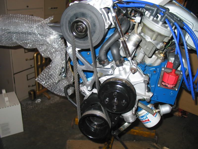
NOTE- That fugly alternator and pulley were soon replaced. The internal voltage regulator was shot on this one anyway. An MC forum member had a spare alternator, and generously sent it to me.
Initially I think I may give it a shot as is. A couple of other builders have done it with this routing, and so far, have had no problems with slipage. The trick is to get the belt pretty snug initially, then re-check, and tighten further if required, after a few engine heat cycles.
NOTE- 5000+ miles later, the belt has never so much as uttered a squeal. Works like a hot damn..
SERPENTINE BELT
NOTE- That fugly alternator and pulley were soon replaced. The internal voltage regulator was shot on this one anyway. An MC forum member had a spare alternator, and generously sent it to me.
Last edited:
AC Bill
Well-known member
I have been working on several things the last few weeks. Some are perhaps not all that interesting, so I have waited to post, until I could get a few pictures showing progress that is obvious.
I needed to finish adding wire harness attachments to several areas of the wire harness. In some cases I used the rubber insulated metal band type, which I riveted, or screwed to the frame. Seen here.
Steel Tubing Clamps With Neoprene Jacket
I also found some nifty attachments that use a zap strap to support harness's. They are riveted or screwed to the chassis, at spaced intervals along the harness to be supported. You then simply run a zap strap through them, and around the harness, to snug it up. They are especially handy if you need to have a little slack, or play, in the harness, as you simply don't tighten the zap strap all the way closed.
DASH MATERIAL APPLIED.
I also decided to tackle the job of covering the aluminum dash with the material that is provided in the kit. It is a pre-padded vinyl material, that is supposed to simulate leather, (I guess). It is slightly larger than the dash to allow you to overlap the edges, and glue the material to the back of the dash as well, for that finished look.
First I cleaned the aluminum dash face with acetone, after roughing up the surface with a scotch pad quite well. You also do the same to the areas of the back of the dash that the material will fold over to be glued. This is to help the adhesive stick to the aluminum.
Then I laid the dash aluminum face up, on a clean flat surface, with the dash cover material nearby. I spray the 3-M Super 90 adhesive on the the dash, and also sprayed the vinyl at the same time. Your supposed to let it tack up slightly before joining the two. Carefully, starting at the middle of the dash, I laid the material over the aluminum. It helps to have an extra set of hands for this, to insure that the material is centered properly. Using a small paint roller, I smoothed the vinyl from the center toward the dash ends, trying to remove any air pockets, or wrinkles. The material lays down pretty nice, and I was happy with how it looked.
After this has had a few hours to dry, I flipped the dash over, and began to glue the areas that overlap behind the dash, down. As the material has a tendency to want to spring back, (I think mainly because of the padding), I needed to fasten it firmly until it dried. Using paint stir sticks, (new clean ones), on the front of the dash edges, and large spring clamps, I was able to hold the material firmly until it dried. The stir sticks prevent the clamps from leaving compression marks on the vinyl, as they spread the tension out. I left them on overnight.
The following day, I needed to cut the openings in the dash vinyl for all the gauges, indicator lights and switches. I used a new very sharp x-acto knife for this. Some builders cut the material in a star pattern, and glue the overlap to the back of the dash. Personally this seemed like a lot of excess material, especially on the large speedo and tach holes. As well, the brackets that hold the gauges to the dash were not long enough to reach over the studs on the back of the gauges, with that excess material in the way. I simply cut holes slightly smaller than the gauges, and then cut reliefs in the material, to allow it to fold back inward, as the gauge was slid into place. The gauges held this excess material quite well, as they were a tight fit especially with the dash padding, and I didn't bother to use any glue.
Next were the holes for the switches, indicator lights, and also the holes previously drilled to mount the dash to the frame. Being these are quite small, 1/2" or smaller, I used a trick that I had read about, that is also used for making holes in carpeting and the cockpit insulation. Using a small propane torch, I heated up a nail, held in a pair of vice grips, and ran it through the dash material. It melted very quickly, and left nice uniform holes, with no ragged edges, as one might get if they tried cutting them. I had to reheat the nail a few times on the larger holes, to keep it from sticking, and to ensure smooth holes. Works great!
I was able to mount the gauges, and indicator lights, as they go in from the front of the dash. The toggle, heater, and headlight switches I had to do later as they go in from behind, to be fastened. The indicator lights are supposed to be pressure fit, but I wasn't happy with the resistance, to keep them in place solidly. I had read of this problem on the FFR builders forum, so I was prepared, and had previously bought some metal clips that slip over the back of the light, and hold them firmly in place. I needed the 1/2" id ones. These clips can be seen here.
ClipsAndFasteners.com - Automotive Retainers,Clips and Fasteners
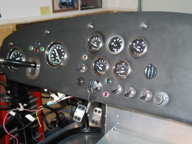
DASH PICTURES
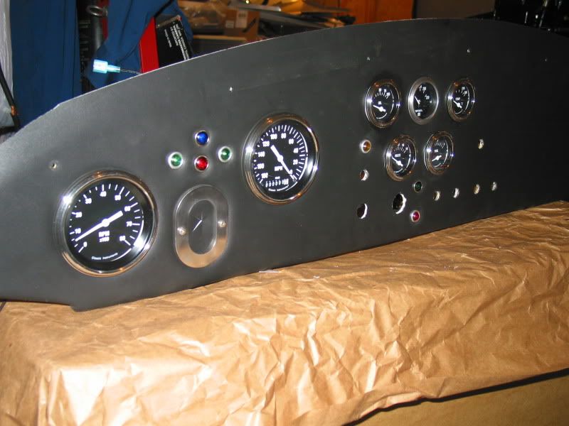
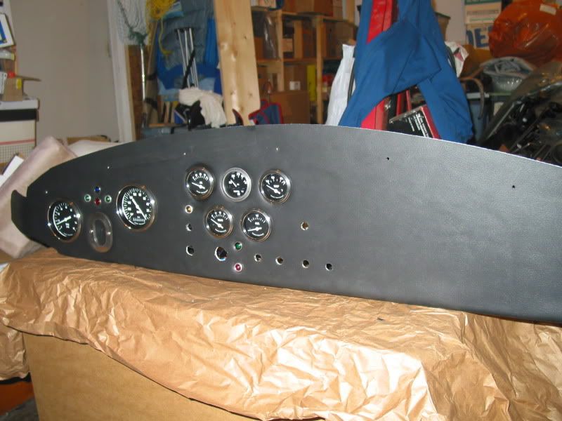
That is a reverse read 0-180mph speedo installed, which was used on many of the original Cobras, in case you were wondering why the needle is on the wrong side of the gauge face. All the gauges are made by Classic Instruments, with the exceprion of the oil temp gauge, which is Stewart Warner. Classic's set came as a six gauge set, with the option of adding a clock, or oil temp gauge. I realised later, that I probably should have ordered one of them at the same time, as the rest of the gauges, as they come from the US. The Stewart Warner was available locally, and I thought it looked similar enough to the others, so I added that to the set.
The steering column bezel is made of stainless steel, and was made by a fellow in Vancouver, who also made the roll bar, and windshield post bezels. It finishes off the hole that the column goes through. I slit the dash cover in a star pattern for the column to go through.
DASH INSTALLATION
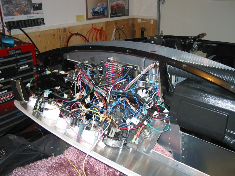
I placed the dash in the cockpit, and began the laborious process of installing the switches, and gauge sensor wires, indicator light wires, ground and power wires. Not easy when you have big hands. I am amazed at how much wire is stuffed into this area, and have some concerns about how I am going to find room to run my other two heater duct hoses, that need to come over to the drivers side, for foot box heat, and defroster vent..Should be interesting to say the least..
I will spend some time gathering all the dash wires as much as possible, and wrapping them, so it should much neater when finished.
I needed to finish adding wire harness attachments to several areas of the wire harness. In some cases I used the rubber insulated metal band type, which I riveted, or screwed to the frame. Seen here.
Steel Tubing Clamps With Neoprene Jacket
I also found some nifty attachments that use a zap strap to support harness's. They are riveted or screwed to the chassis, at spaced intervals along the harness to be supported. You then simply run a zap strap through them, and around the harness, to snug it up. They are especially handy if you need to have a little slack, or play, in the harness, as you simply don't tighten the zap strap all the way closed.
DASH MATERIAL APPLIED.
I also decided to tackle the job of covering the aluminum dash with the material that is provided in the kit. It is a pre-padded vinyl material, that is supposed to simulate leather, (I guess). It is slightly larger than the dash to allow you to overlap the edges, and glue the material to the back of the dash as well, for that finished look.
First I cleaned the aluminum dash face with acetone, after roughing up the surface with a scotch pad quite well. You also do the same to the areas of the back of the dash that the material will fold over to be glued. This is to help the adhesive stick to the aluminum.
Then I laid the dash aluminum face up, on a clean flat surface, with the dash cover material nearby. I spray the 3-M Super 90 adhesive on the the dash, and also sprayed the vinyl at the same time. Your supposed to let it tack up slightly before joining the two. Carefully, starting at the middle of the dash, I laid the material over the aluminum. It helps to have an extra set of hands for this, to insure that the material is centered properly. Using a small paint roller, I smoothed the vinyl from the center toward the dash ends, trying to remove any air pockets, or wrinkles. The material lays down pretty nice, and I was happy with how it looked.
After this has had a few hours to dry, I flipped the dash over, and began to glue the areas that overlap behind the dash, down. As the material has a tendency to want to spring back, (I think mainly because of the padding), I needed to fasten it firmly until it dried. Using paint stir sticks, (new clean ones), on the front of the dash edges, and large spring clamps, I was able to hold the material firmly until it dried. The stir sticks prevent the clamps from leaving compression marks on the vinyl, as they spread the tension out. I left them on overnight.
The following day, I needed to cut the openings in the dash vinyl for all the gauges, indicator lights and switches. I used a new very sharp x-acto knife for this. Some builders cut the material in a star pattern, and glue the overlap to the back of the dash. Personally this seemed like a lot of excess material, especially on the large speedo and tach holes. As well, the brackets that hold the gauges to the dash were not long enough to reach over the studs on the back of the gauges, with that excess material in the way. I simply cut holes slightly smaller than the gauges, and then cut reliefs in the material, to allow it to fold back inward, as the gauge was slid into place. The gauges held this excess material quite well, as they were a tight fit especially with the dash padding, and I didn't bother to use any glue.
Next were the holes for the switches, indicator lights, and also the holes previously drilled to mount the dash to the frame. Being these are quite small, 1/2" or smaller, I used a trick that I had read about, that is also used for making holes in carpeting and the cockpit insulation. Using a small propane torch, I heated up a nail, held in a pair of vice grips, and ran it through the dash material. It melted very quickly, and left nice uniform holes, with no ragged edges, as one might get if they tried cutting them. I had to reheat the nail a few times on the larger holes, to keep it from sticking, and to ensure smooth holes. Works great!
I was able to mount the gauges, and indicator lights, as they go in from the front of the dash. The toggle, heater, and headlight switches I had to do later as they go in from behind, to be fastened. The indicator lights are supposed to be pressure fit, but I wasn't happy with the resistance, to keep them in place solidly. I had read of this problem on the FFR builders forum, so I was prepared, and had previously bought some metal clips that slip over the back of the light, and hold them firmly in place. I needed the 1/2" id ones. These clips can be seen here.
ClipsAndFasteners.com - Automotive Retainers,Clips and Fasteners
DASH PICTURES
That is a reverse read 0-180mph speedo installed, which was used on many of the original Cobras, in case you were wondering why the needle is on the wrong side of the gauge face. All the gauges are made by Classic Instruments, with the exceprion of the oil temp gauge, which is Stewart Warner. Classic's set came as a six gauge set, with the option of adding a clock, or oil temp gauge. I realised later, that I probably should have ordered one of them at the same time, as the rest of the gauges, as they come from the US. The Stewart Warner was available locally, and I thought it looked similar enough to the others, so I added that to the set.
The steering column bezel is made of stainless steel, and was made by a fellow in Vancouver, who also made the roll bar, and windshield post bezels. It finishes off the hole that the column goes through. I slit the dash cover in a star pattern for the column to go through.
DASH INSTALLATION
I placed the dash in the cockpit, and began the laborious process of installing the switches, and gauge sensor wires, indicator light wires, ground and power wires. Not easy when you have big hands. I am amazed at how much wire is stuffed into this area, and have some concerns about how I am going to find room to run my other two heater duct hoses, that need to come over to the drivers side, for foot box heat, and defroster vent..Should be interesting to say the least..
I will spend some time gathering all the dash wires as much as possible, and wrapping them, so it should much neater when finished.
AC Bill
Well-known member
HIGH/LOW BEAM SWITCH
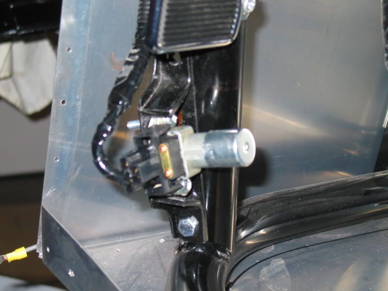
I also worked on the positioning and installation of the high/low beam dimmer switch.
I used a GM style floor dimmer switch which can handle enough amperage that I don't need to add a relay for this. Some builders use a simple dash toggle switch, but have found the need to wire in a relay, otherwise the switch can overheat.
First I had to establish where to mount this switch which necessitated placing the seat in the chassis, and sitting down. I had a buddy who held the switch in different locations, to be sure I could reach it, as well as it wouldn't interfere with the pedals etc. Once we found a good spot for it, we had to make a bracket to mount it. Once again a trip to my "never throw out as you may need it one day" junk box, produced a suitable piece of bracket. It needed very little modification, and as a bonus was already powder coated black! As the switch needs to sit on a bit of an angle upward, we had to cut and drill a small piece of aluminum channel to fit between the switch and the bracket. We mounted it all below my dead pedal, onto the frame tubing, which is a solid spot. Here is the result.
DIMMER SWITCH
AC Bill
Well-known member
As to tearing down a perfectly good Mustang to build a FFR. It does seem almost a sin to break up a perfectly good Mustang to use as a donor, rather than using a wreck, but it does have it's good points. You know that the parts are all functioning correctly, the engine runs good, tranny shifts, rear end is solid, etc., vs taking a risk on buying parts off a car sitting in the wrecking yard, that you can't actually drive, or perhaps even start. The deciding factor depends a lot on the budget that a builder can handle. Obviously a good running Mustang that is still street-able, is going to cost you more initially.
In some cases though much of the initial cost for the vehicles purchase can be made back on selling parts off it, (after you have stripped it down of the items you need for your build). Some fellows have been so successful at this. that the cost of the donor parts is actually less then if you bought them separately at a wrecker.
BUILD CONTINUES
In between working in the garden, and a trip to Vancouver, I managed to get a few more things done on the Cobra.
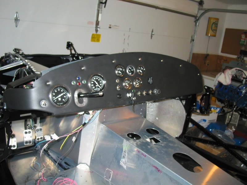
I have now mounted the dash to the chassis, and installed the switches. I did manage to find room for the heater ductwork, but it was quite a squeeze. You can also see in these pictures, the tranny console that I modified for an original Cobra style ashtray, and two un-original stainless steel cup holders. The ashtray won't be used for ashes by the way....and the cup holders won't be used for beer cans..unless it's parked in my own driveway..lol.. I used a 3" bi-metal hole saw for the cup holders, and a drill and a dremel cutting wheel for the ashtray hole.
The console will eventually be covered in vinyl to match the dash. Future builders may want to note, that the stainless steel cup holders are available in most marine stores. The ashtray (brand new) I bought from an e-bayer in England. They are common on many British cars.
DASH MOUNTED
I also drilled some holes in the frame for mounting ground straps from the engine. Good grounds are crucial for the EFI builds especially, as well as a good ground for the starter. The LeMans style fuel filler cap needs to be grounded as well, to prevent static discharge, (being the body is fiberglass). I will also run a extra ground off the fuel tank itself. You can simply use 10 or 12 gauge wire for these grounds, rather than the heavy straps.
I need to install a new rear main seal, (better to to it now while the engine is still out), as well I have a new clutch pilot bearing to be installed. This means taking the 302 off the engine stand. One of my concerns in doing this was to prevent damage to my nice clean, freshly painted engine. I rec'd some good advice on using split rubber hose, or towels on the engine hoist chains in the areas they may rub the valve covers or intake plenum. A good friend made a chain spreader that I can use to lift the engine using the factory hoist brackets, for the time being. They spread the chains out enough that they do not "pinch" the engine, when lifted.
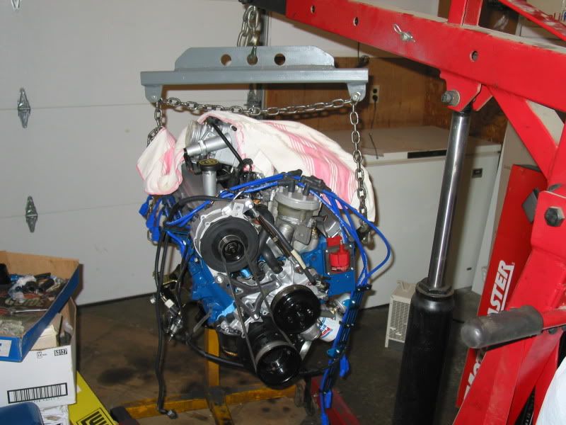
I bought an engine leveler, but it is designed to use the intake manifold as a lifting point, as it is not as long as the chain spreader pictured above. This will mean removing the intake plenum, which I was hoping not to have to do, but I may have no choice in the end, unless I add new chains to the leveler, The ones that come with it are to short to reach the engine's original hoist brackets.
The majority of builders drop the engine into the frame, with the tranny already bolted on. This means you need a good way of angling the engine/tranny to get it to slide into the tranny tunnel properly. I can't see how I can accomplish this without the engine leveler being used. Using the chain spreader pictured, I can't envision how I could angle the engine/tranny correctly to install it.
(I am still looking for a donation of a nicer looking alternator pulley, if anyone has one they can spare..)
Before I move on to this step, I am going to re-check the torque on all my steering, and front and rear suspension. I will also grease the upper and lower ball joints, the front upper control arm mounting points, and the rear suspension lower control arms bushings. (The BBK control arms I have have four grease fittings, unlike the stock Mustang ones) The use of synthetic silicone based grease is used for these, as regular petroleum based greases can damage the polyurethane bushings. I am also going to top up the rear differential, with the proper gear oil.
Once this is all done I will mount the wheels and tires and lower the chassis to the ground. It's easier to do all this stuff now, while the chassis is still on the sawhorses.
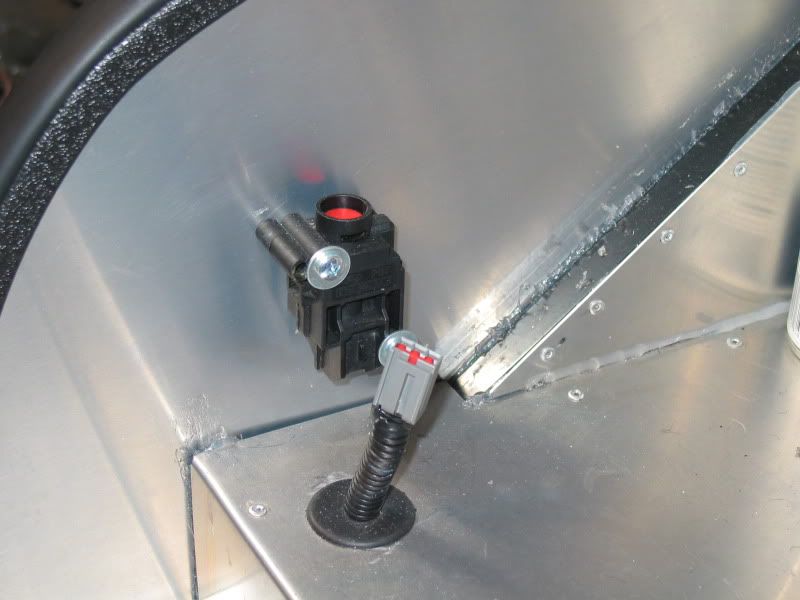
The stock Mustang fuel pump inertia switch is recommended to be used, just in case..I mounted mine inside the trunk, similar to the original Mustang location, for easy access. Once again a PCV valve grommet works perfect as a wire harness pass thru, and to protect the wire from chaffing on the sharp aluminum.
INERTIA SWITCH
In some cases though much of the initial cost for the vehicles purchase can be made back on selling parts off it, (after you have stripped it down of the items you need for your build). Some fellows have been so successful at this. that the cost of the donor parts is actually less then if you bought them separately at a wrecker.
BUILD CONTINUES
In between working in the garden, and a trip to Vancouver, I managed to get a few more things done on the Cobra.
I have now mounted the dash to the chassis, and installed the switches. I did manage to find room for the heater ductwork, but it was quite a squeeze. You can also see in these pictures, the tranny console that I modified for an original Cobra style ashtray, and two un-original stainless steel cup holders. The ashtray won't be used for ashes by the way....and the cup holders won't be used for beer cans..unless it's parked in my own driveway..lol.. I used a 3" bi-metal hole saw for the cup holders, and a drill and a dremel cutting wheel for the ashtray hole.
The console will eventually be covered in vinyl to match the dash. Future builders may want to note, that the stainless steel cup holders are available in most marine stores. The ashtray (brand new) I bought from an e-bayer in England. They are common on many British cars.
DASH MOUNTED
I also drilled some holes in the frame for mounting ground straps from the engine. Good grounds are crucial for the EFI builds especially, as well as a good ground for the starter. The LeMans style fuel filler cap needs to be grounded as well, to prevent static discharge, (being the body is fiberglass). I will also run a extra ground off the fuel tank itself. You can simply use 10 or 12 gauge wire for these grounds, rather than the heavy straps.
I need to install a new rear main seal, (better to to it now while the engine is still out), as well I have a new clutch pilot bearing to be installed. This means taking the 302 off the engine stand. One of my concerns in doing this was to prevent damage to my nice clean, freshly painted engine. I rec'd some good advice on using split rubber hose, or towels on the engine hoist chains in the areas they may rub the valve covers or intake plenum. A good friend made a chain spreader that I can use to lift the engine using the factory hoist brackets, for the time being. They spread the chains out enough that they do not "pinch" the engine, when lifted.
I bought an engine leveler, but it is designed to use the intake manifold as a lifting point, as it is not as long as the chain spreader pictured above. This will mean removing the intake plenum, which I was hoping not to have to do, but I may have no choice in the end, unless I add new chains to the leveler, The ones that come with it are to short to reach the engine's original hoist brackets.
The majority of builders drop the engine into the frame, with the tranny already bolted on. This means you need a good way of angling the engine/tranny to get it to slide into the tranny tunnel properly. I can't see how I can accomplish this without the engine leveler being used. Using the chain spreader pictured, I can't envision how I could angle the engine/tranny correctly to install it.
(I am still looking for a donation of a nicer looking alternator pulley, if anyone has one they can spare..)
Before I move on to this step, I am going to re-check the torque on all my steering, and front and rear suspension. I will also grease the upper and lower ball joints, the front upper control arm mounting points, and the rear suspension lower control arms bushings. (The BBK control arms I have have four grease fittings, unlike the stock Mustang ones) The use of synthetic silicone based grease is used for these, as regular petroleum based greases can damage the polyurethane bushings. I am also going to top up the rear differential, with the proper gear oil.
Once this is all done I will mount the wheels and tires and lower the chassis to the ground. It's easier to do all this stuff now, while the chassis is still on the sawhorses.
The stock Mustang fuel pump inertia switch is recommended to be used, just in case..I mounted mine inside the trunk, similar to the original Mustang location, for easy access. Once again a PCV valve grommet works perfect as a wire harness pass thru, and to protect the wire from chaffing on the sharp aluminum.
INERTIA SWITCH
AC Bill
Well-known member
I have been busy the last week trying to get everything done that needed to be done while the chassis was still up on the sawhorses. Access to the underside has been great having it up so high, and I kind of hate dropping it down, as I know I will never be able to get it up that high again, unless it's on a hoist..which sadly I don't have...maybe if I win a Lottery..
So I re-checked all the suspension and steering components for proper torque, and greased what I could. I was disappointed to see the boots on both upper and lower ball joints had slipped. I can't really fill these with grease until I get them back on. I think the cause was the suspension was sitting at full droop all this time, and the boots were under some pressure. How to get them back into place I'm not sure as they are pretty stiff, being brand new. This style of boot doesn't have any wire ring or band to retain them.. Any tips on doing this??
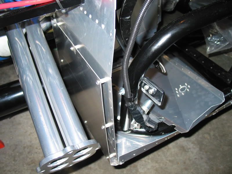
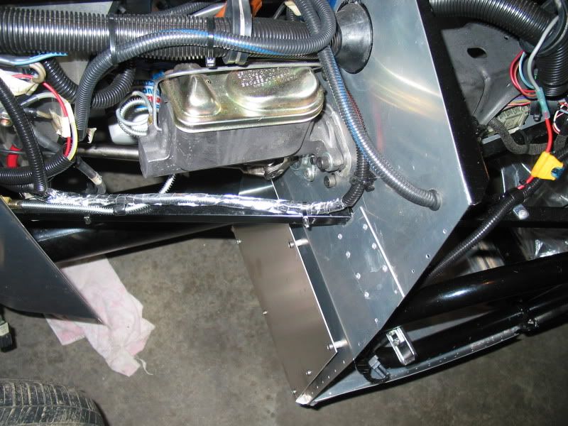
I also had to install a drivers front foot box protector panel. This will serve a two fold purpose. One, to add protection from road debris penetrating the front or underside of the foot box, as there is only one thin sheet of aluminum used in these areas. Two, it will act as a heat deflector on my rearbrake line which runs down from the master cylinder, and is quite close to the BBK headers.
This job entailed having a piece of thicker aluminum bent after measuring, on a metal brake. A local company that does sheet metal work did this for me, (on the house yet!), which was handy. After clamping it in place I had to drill holes through it, and the front and underside of the existing foot box panels. I bought some small diameter aluminum pipe, which I cut to make spacers, to be able to "stand off" the panel on the front foot box area. Then using pan-head screws and locknut's, I ran them through the new panel, through the spacer, and attached the nuts on the inside of the original foot box panel. On the underside, I attached the new panel with several rivets directly, as it sits flush with the floor board.
I was happy with the final result, although after temporarily hanging the headers, I can see I could have made the panel taller at the front, to cover more of the brake line. I may just use a thermo protective sleeve for 4"-5" on the line, or perhaps a piece of aluminum channel. I suppose I could even fabricate a small piece of aluminum, and simply rivet it on over the line.
FOOT BOX PROTECTION MODIFICATION
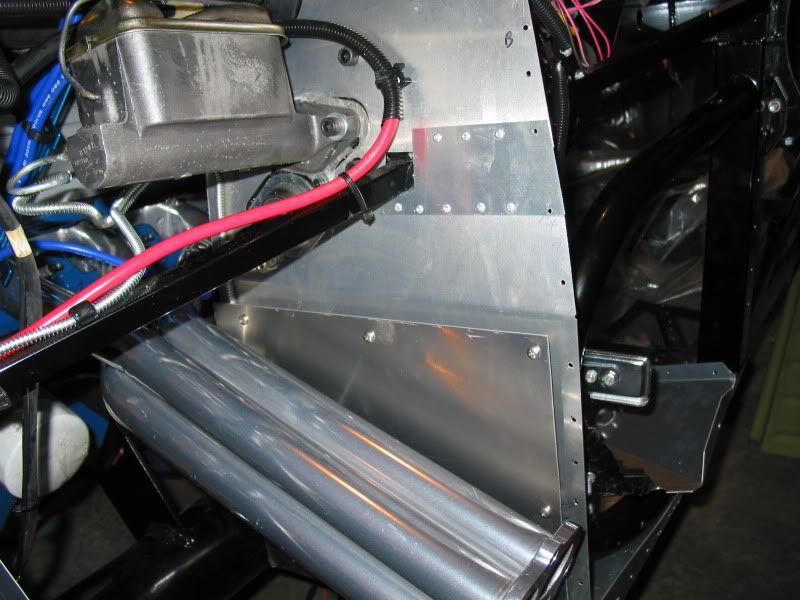
You can just barely see the front brake line in these photos, but you can see what I meant by some of it still being unprotected from the header heat. The heat may not be a problem as the headers are ceramic coated, which is supposed to reduce the heat. Some builders have complained that they were finding a pressure build up in their brake system, which they attributed to brake fluid expansion. I am not really sure of the way they plumbed their systems though, so this again may not be a factor with mine. Thought I would do what I could anyway, to stave off potential problems down the road.
So after all the stuff I could think of that may need to be done, we had to lower the frame down off the sawhorses. We looked at a few different ways of doing this safely, but finally came up with the idea of using two engine hoists, one on the front, one on the rear. We wrapped some nylon pull straps on the rear end, around the main frame. The front end we had to use chains around the front X member, as lifting points. We the carefully jacked the entire frame up, slipped out the sawhorses, and then lowered it down on to floor jacks. I didn't want it all the way down on the floor, as I would need to get under the car still to attach the transmission carrier, fuel lines, oil temp sending unit wire harness, 02 wire harness, etc. I also needed to have enough clearance to slide the legs of the engine hoist under the car, when doing the engine install.
I wish I had a picture of it hanging off the engine hoists, as it was something to see, but I had no extra people to handle the camera.
FINALIZING ENGINE PRIOR TO INSTALL.
To get the engine finalized before install, I had to remove the old pilot bearing, and install the new one. I used the grease pack method for this job, and it worked great. Simply fill the center of the pilot bearing as much as you can with grease. Next get a proper sized socket, with a bolt through the center of it, and a nut to hold the bolt firmly in the socket. I also wrapped some black tape around the outside of the socket to create a better seal. Insert the socket into the center hole of the pilot bearing, bolt head first. Whack it with a hammer a couple of times, and the grease that you packed in, forces the pilot bearing out, with hydraulic pressure. Neat trick if you don't have the specialized puller on hand!
I then drilled a small hole through the rear main seal, being careful not to mar the crank surface or the block. Insert a tap screw into the hole, then using a hammer, we pried out the seal. You may have to use two screws, one on either dies of the seal, to do this, but we managed with just the one, as I think the seal was rather dry from sitting. The new seal we carefully installed using a block of wood, and a rubber mallet. The seal had a slight skim of RTV around the outside lip, and grease on the inside lip. This should be done from all I have read.
That done I put the engine back on the engine stand, and spun it upside down, to install the oil pan, and gasket. I have a new style Fel-Pro one piece silicone gasket. According to the instructions you don't use any RTV in the corners by the crank rounds in the pan. I hope like hell this actually still seals it properly, as with most gaskets, you do use some RTV at these points. Anybody use these oil pan gaskets before? How did they work??
I then installed the block plate, freshly machined flywheel, clutch assembly, throwout bearing, and then the transmission itself. The Powermaster high torque starter was also installed.
Although they would be removed later, I had to put the two black engine hoisting brackets back on the engine. This year 5.0 has one on the right rear, and one on the left front, attached by exhaust manifold bolts. They are marked clearly which bracket is to go where, and which way round. I found that by actually using the front one on the rear, and the rear on the front, and turning one around the opposite way it was to face the heads, it allowed for better positioning of the chains, for hoisting. It allowed less contact on the engine from the hoist chains, so less chance to mar the fresh paint. Very cool, as I was worried about that aspect!
Lastly, I mounted the tranny support cradle, and the new Energy Suspension tranny mount. The suppost cradle (that comes with the kit) is bolted onto the 4" main frame tubes. It took a bit of work to get it to fit in, as some of the factory weld beads, were preventing the bolt holes from lining up. A little grinding on the beads, as well as filing the frame holes helped get it all straight.
ENGINE INSTALL
I had two friends on hand to help do the engine install. I really can't see doing this yourself, even with two guys it would be a bit of a trick. Being the tranny is already bolted to the engine, you have to thread it up inside the tranny tunnel. Someone was needed to help guide the tranny into place. It also takes one guy to work the jack, and one to check for things lining up, and kind of shoving the engine around to do so, on it's way down to the engine mounts.
I was very pleased how it all went. It only took about twenty minutes to get it in and sitting on the mounts. It tooka bit of wiggling to get the engine mount bolts to line up perfect, but no damage to the engine, rad, firewall, or helpers, so all was good!
Again, I wish I had pictures of this process, but nobody extra there to handle the camera..Heres a few of the engine in place.
ENGINE IN!
So now begins the process of hooking up all engine electrical, fuel lines, heater, and rad hoses, etc..
The headers also need to be installed, but I am waiting for a set of Percy Splitlock bolts from Lordco. I did manage to finally get a set of Remflexexhaust manifold gaskets, as Lordco is now handling the Remflex product line. These thicker gaskets apparently prevent the exhaust gas leaks that seem to be common, when using these 4 into 4 headers. I read that some don't even bother with gaskets, and have had good luck using the high heat copper RTV only. Time will tell..
So I re-checked all the suspension and steering components for proper torque, and greased what I could. I was disappointed to see the boots on both upper and lower ball joints had slipped. I can't really fill these with grease until I get them back on. I think the cause was the suspension was sitting at full droop all this time, and the boots were under some pressure. How to get them back into place I'm not sure as they are pretty stiff, being brand new. This style of boot doesn't have any wire ring or band to retain them.. Any tips on doing this??
I also had to install a drivers front foot box protector panel. This will serve a two fold purpose. One, to add protection from road debris penetrating the front or underside of the foot box, as there is only one thin sheet of aluminum used in these areas. Two, it will act as a heat deflector on my rearbrake line which runs down from the master cylinder, and is quite close to the BBK headers.
This job entailed having a piece of thicker aluminum bent after measuring, on a metal brake. A local company that does sheet metal work did this for me, (on the house yet!), which was handy. After clamping it in place I had to drill holes through it, and the front and underside of the existing foot box panels. I bought some small diameter aluminum pipe, which I cut to make spacers, to be able to "stand off" the panel on the front foot box area. Then using pan-head screws and locknut's, I ran them through the new panel, through the spacer, and attached the nuts on the inside of the original foot box panel. On the underside, I attached the new panel with several rivets directly, as it sits flush with the floor board.
I was happy with the final result, although after temporarily hanging the headers, I can see I could have made the panel taller at the front, to cover more of the brake line. I may just use a thermo protective sleeve for 4"-5" on the line, or perhaps a piece of aluminum channel. I suppose I could even fabricate a small piece of aluminum, and simply rivet it on over the line.
FOOT BOX PROTECTION MODIFICATION
You can just barely see the front brake line in these photos, but you can see what I meant by some of it still being unprotected from the header heat. The heat may not be a problem as the headers are ceramic coated, which is supposed to reduce the heat. Some builders have complained that they were finding a pressure build up in their brake system, which they attributed to brake fluid expansion. I am not really sure of the way they plumbed their systems though, so this again may not be a factor with mine. Thought I would do what I could anyway, to stave off potential problems down the road.
So after all the stuff I could think of that may need to be done, we had to lower the frame down off the sawhorses. We looked at a few different ways of doing this safely, but finally came up with the idea of using two engine hoists, one on the front, one on the rear. We wrapped some nylon pull straps on the rear end, around the main frame. The front end we had to use chains around the front X member, as lifting points. We the carefully jacked the entire frame up, slipped out the sawhorses, and then lowered it down on to floor jacks. I didn't want it all the way down on the floor, as I would need to get under the car still to attach the transmission carrier, fuel lines, oil temp sending unit wire harness, 02 wire harness, etc. I also needed to have enough clearance to slide the legs of the engine hoist under the car, when doing the engine install.
I wish I had a picture of it hanging off the engine hoists, as it was something to see, but I had no extra people to handle the camera.
FINALIZING ENGINE PRIOR TO INSTALL.
To get the engine finalized before install, I had to remove the old pilot bearing, and install the new one. I used the grease pack method for this job, and it worked great. Simply fill the center of the pilot bearing as much as you can with grease. Next get a proper sized socket, with a bolt through the center of it, and a nut to hold the bolt firmly in the socket. I also wrapped some black tape around the outside of the socket to create a better seal. Insert the socket into the center hole of the pilot bearing, bolt head first. Whack it with a hammer a couple of times, and the grease that you packed in, forces the pilot bearing out, with hydraulic pressure. Neat trick if you don't have the specialized puller on hand!
I then drilled a small hole through the rear main seal, being careful not to mar the crank surface or the block. Insert a tap screw into the hole, then using a hammer, we pried out the seal. You may have to use two screws, one on either dies of the seal, to do this, but we managed with just the one, as I think the seal was rather dry from sitting. The new seal we carefully installed using a block of wood, and a rubber mallet. The seal had a slight skim of RTV around the outside lip, and grease on the inside lip. This should be done from all I have read.
That done I put the engine back on the engine stand, and spun it upside down, to install the oil pan, and gasket. I have a new style Fel-Pro one piece silicone gasket. According to the instructions you don't use any RTV in the corners by the crank rounds in the pan. I hope like hell this actually still seals it properly, as with most gaskets, you do use some RTV at these points. Anybody use these oil pan gaskets before? How did they work??
I then installed the block plate, freshly machined flywheel, clutch assembly, throwout bearing, and then the transmission itself. The Powermaster high torque starter was also installed.
Although they would be removed later, I had to put the two black engine hoisting brackets back on the engine. This year 5.0 has one on the right rear, and one on the left front, attached by exhaust manifold bolts. They are marked clearly which bracket is to go where, and which way round. I found that by actually using the front one on the rear, and the rear on the front, and turning one around the opposite way it was to face the heads, it allowed for better positioning of the chains, for hoisting. It allowed less contact on the engine from the hoist chains, so less chance to mar the fresh paint. Very cool, as I was worried about that aspect!
Lastly, I mounted the tranny support cradle, and the new Energy Suspension tranny mount. The suppost cradle (that comes with the kit) is bolted onto the 4" main frame tubes. It took a bit of work to get it to fit in, as some of the factory weld beads, were preventing the bolt holes from lining up. A little grinding on the beads, as well as filing the frame holes helped get it all straight.
ENGINE INSTALL
I had two friends on hand to help do the engine install. I really can't see doing this yourself, even with two guys it would be a bit of a trick. Being the tranny is already bolted to the engine, you have to thread it up inside the tranny tunnel. Someone was needed to help guide the tranny into place. It also takes one guy to work the jack, and one to check for things lining up, and kind of shoving the engine around to do so, on it's way down to the engine mounts.
I was very pleased how it all went. It only took about twenty minutes to get it in and sitting on the mounts. It tooka bit of wiggling to get the engine mount bolts to line up perfect, but no damage to the engine, rad, firewall, or helpers, so all was good!
Again, I wish I had pictures of this process, but nobody extra there to handle the camera..Heres a few of the engine in place.
ENGINE IN!
So now begins the process of hooking up all engine electrical, fuel lines, heater, and rad hoses, etc..
The headers also need to be installed, but I am waiting for a set of Percy Splitlock bolts from Lordco. I did manage to finally get a set of Remflexexhaust manifold gaskets, as Lordco is now handling the Remflex product line. These thicker gaskets apparently prevent the exhaust gas leaks that seem to be common, when using these 4 into 4 headers. I read that some don't even bother with gaskets, and have had good luck using the high heat copper RTV only. Time will tell..
AC Bill
Well-known member
I am hoping for a donation of 16 lug nuts in good condition, just in case a member has some old stock ones they replaced sitting in a box on a shelf, gathering dust...Not sure if the thread size has changed since the Fox model, or not? That would be the thread size I am after though.
The lug nuts I currently have are a mix I got no charge from the wrecker, and are all different styles, and in pretty rough shape. I am missing several as well.
I would like the smaller ones, rather than the tall ones that came on some Mustang OEM wheels. I have a set of fake knock off spinners I will be adding, so the less the lug nuts distract from them the better. I may even paint them to match the color of the wheels so they blend in better. I was thinking of painting the wheels a cast metal dark grey color, with a polished rim edge, then clear coated. I can't afford the Cobra style Halibrand wheels at this time, so the Mustang Turbines will have to do.
AC Bill
Well-known member
Ok, so now the engine is in, I began hooking up all the items that feed to it.
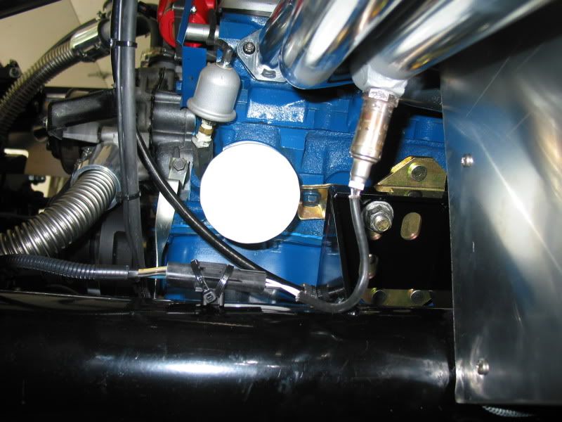
FUEL LINES TO ENGINE
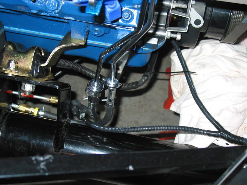
Pretty straight forward doing these. As with any car you need some rubber hose between the steel fuel line, and the engine. This is to allow for engine movement. The rubber hose I bought was fuel injection type hose, that is designed for the higher pressure fuel pump. I also used the fuel injection hose clamps designed for them. Quite a bit more expensive, but I believe its worth it. Being I have the EFI set up I needed 5/16" and 1/4" hose and clamps, to allow for both feed and return lines. I cut the hose to lengths to allow that there would be no kinks, but also that they would not hang down below the frame rail, as this could lead to problems at inspection.
The ends of the lines I ran coming from the tank, had barbed fittings attached to them for the hose to slip over, The stock fuel rails on the engine are already barbed from where the original Mustang hoses attached. The stock rubber hoses had a inner liner that was literally fused to the rails, almost like they were shrink wrapped to them. These had to be cut off, to access the barbs.
In this picture you can see the barbed fitting on the fuel lines just under the engine mount, as well as the new hoses connected to the fuel rails, just below where the stock lines had the spring type connectors.
FUEL LINES
UPPER RAD HOSE
Next came the upper rad hose installation. The kit comes with a length of stainless steel rad hose, that is long enough to do both top and bottom hoses. You also receive 8 hose connectors, that are designed with inserts to allow you to fit the stainless hose to different rads, or engines, depending on what the builder chose to use.
As the radiator filler is very difficult to access once the body is on, many builders use a T filler on the top hose. This set at the highest point of the cooling system also allows for burping air from the system. I first had to attach the stainless hose to the rad, using one of the supplied hose connectors adjusted to the rad inlet size, as well as the stainless hose. As the sizing inserts in the connectors are designed to allow different sizes at either end, I pulled two inserts out of one end to allow for the larger stainless hose, and none from other, to allow for the smaller 1-1/4" rad inlet.
I had to buy a hose that would go from my thermostat housing, to my Moroso T filler, Both the T filler and the T/stat housing were the same diameter, so I had the parts guy find me a proper size hose with a 90* bend in it. The Dayco 70081 was the ticket. I still had to trim some length off either end, but it worked out perfect.
Again I had to use a hose connector between the stainless hose and the T filler. A friend sent me these nifty little aluminum covers designed to hide the connector, (which is quite ugly) to give a more finished appearance. I had hoped for a nicer looking filler cap, but the parts shop didn't have a 16 pound pressure cap on hand, other then the stock replacement.
The last thing I need to do was to hook up the overflow bottle hose to the T fillers spigot. I used a fuel injection hose clamp for this, simply because I thought it looked better than a standard hose clamp. Any clamp would do though, as long as you get a good tight seal, as you don't want it sucking air as the rad cools, rather than coolant from the overflow bottle.
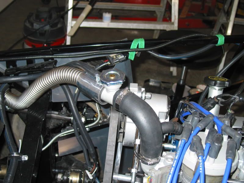
On some FFR's you will see the rad hose run through this opening cut in the front "F" panel,(panel is called this because of its shape). This is to allow for a different rad to be used, that has a rad inlet location different then mine. You get a "block off" panel included in the kit that can be riveted on to close up this opening if it's not used. I will likely do this although I may modify the block off to allow a section of my wire harness that leads to the alternator to pass through it. I haven't decided 100% on it's routing yet, so the block off is not yet in place.
FUEL LINES TO ENGINE
Pretty straight forward doing these. As with any car you need some rubber hose between the steel fuel line, and the engine. This is to allow for engine movement. The rubber hose I bought was fuel injection type hose, that is designed for the higher pressure fuel pump. I also used the fuel injection hose clamps designed for them. Quite a bit more expensive, but I believe its worth it. Being I have the EFI set up I needed 5/16" and 1/4" hose and clamps, to allow for both feed and return lines. I cut the hose to lengths to allow that there would be no kinks, but also that they would not hang down below the frame rail, as this could lead to problems at inspection.
The ends of the lines I ran coming from the tank, had barbed fittings attached to them for the hose to slip over, The stock fuel rails on the engine are already barbed from where the original Mustang hoses attached. The stock rubber hoses had a inner liner that was literally fused to the rails, almost like they were shrink wrapped to them. These had to be cut off, to access the barbs.
In this picture you can see the barbed fitting on the fuel lines just under the engine mount, as well as the new hoses connected to the fuel rails, just below where the stock lines had the spring type connectors.
FUEL LINES
UPPER RAD HOSE
Next came the upper rad hose installation. The kit comes with a length of stainless steel rad hose, that is long enough to do both top and bottom hoses. You also receive 8 hose connectors, that are designed with inserts to allow you to fit the stainless hose to different rads, or engines, depending on what the builder chose to use.
As the radiator filler is very difficult to access once the body is on, many builders use a T filler on the top hose. This set at the highest point of the cooling system also allows for burping air from the system. I first had to attach the stainless hose to the rad, using one of the supplied hose connectors adjusted to the rad inlet size, as well as the stainless hose. As the sizing inserts in the connectors are designed to allow different sizes at either end, I pulled two inserts out of one end to allow for the larger stainless hose, and none from other, to allow for the smaller 1-1/4" rad inlet.
I had to buy a hose that would go from my thermostat housing, to my Moroso T filler, Both the T filler and the T/stat housing were the same diameter, so I had the parts guy find me a proper size hose with a 90* bend in it. The Dayco 70081 was the ticket. I still had to trim some length off either end, but it worked out perfect.
Again I had to use a hose connector between the stainless hose and the T filler. A friend sent me these nifty little aluminum covers designed to hide the connector, (which is quite ugly) to give a more finished appearance. I had hoped for a nicer looking filler cap, but the parts shop didn't have a 16 pound pressure cap on hand, other then the stock replacement.
The last thing I need to do was to hook up the overflow bottle hose to the T fillers spigot. I used a fuel injection hose clamp for this, simply because I thought it looked better than a standard hose clamp. Any clamp would do though, as long as you get a good tight seal, as you don't want it sucking air as the rad cools, rather than coolant from the overflow bottle.
On some FFR's you will see the rad hose run through this opening cut in the front "F" panel,(panel is called this because of its shape). This is to allow for a different rad to be used, that has a rad inlet location different then mine. You get a "block off" panel included in the kit that can be riveted on to close up this opening if it's not used. I will likely do this although I may modify the block off to allow a section of my wire harness that leads to the alternator to pass through it. I haven't decided 100% on it's routing yet, so the block off is not yet in place.
AC Bill
Well-known member
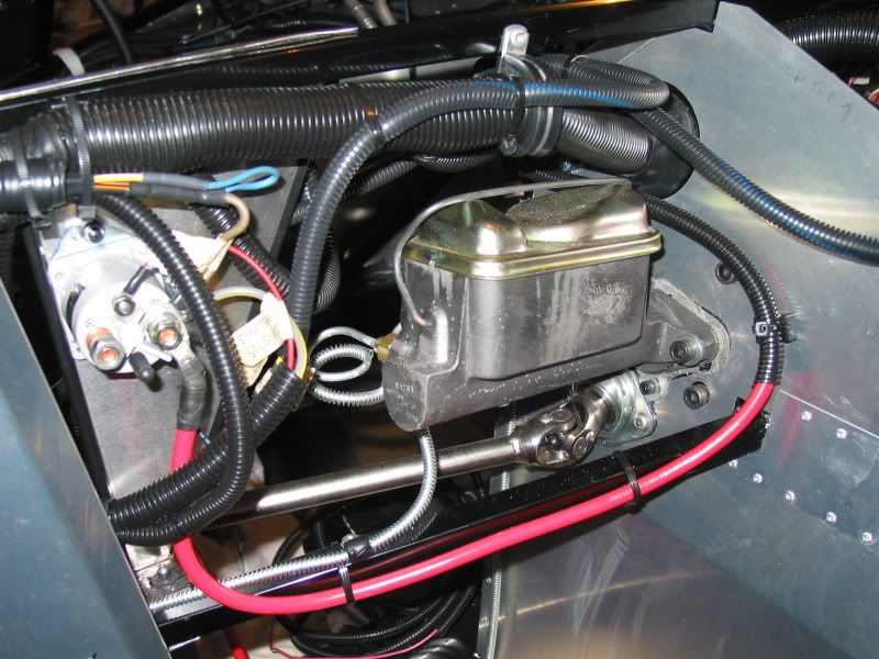
STARTER WIRING
. I am using the Powermaster XS high torque mini starter, that came with the donor parts. I don't know why the previous owner of the Mustang GT had this starter, but I figure the factory Ford one must have failed at some point, so he opted for one of these to replace it. They are more commonly used on engines that have been " warmed over" a bit. It's ok with me, as it is smaller and lighter than the OEM one.
As I still have used a stock FOX type remote starter solenoid, I needed to wire the starter in such a way as to prevent starter "run on" which apparently is quite common for this style aftermarket starters. The fellows that have had these issues, usually use a jump wire between the smaller starters solenoid post, and the larger +12V post. This engages the starters solenoid when the key is turned on, and the stock remote solenoid sends power down the main power cable. Some speculate that the starter spinning actually creates an electrical feedback that keeps the starters solenoid triggered, thus inducing the "run on" problem.
You could wire the battery cable and ignition start wire directly to the starter, without using a stock type remote starter solenoid at all. This would eliminate the run on issue. Many builders do it this way.
In my case, as with other builders, we need to use the remote solenoid to attach several other items that require +12V power. Using the donor wire harness's, this is common because of the harness routing, leading to the area that the remote solenoid is normally mounted in the Mustang (79-93 years at least).
To wire the mini starter using the remote solenoid, I ran the
stock donor heavy gauge cable from the "always hot" side of the remote solenoid, to the large post on the starter. I then ran a 10 Ga wire, from the other post on the remote solenoid, (that is "triggered" when the ignition switch is turned on) to the smaller post on the starter, to engage it's built in solenoid.
I used the wire routing for both cable and 10 Ga wire, the same way as the stock Mustang configuration. This makes use of the two brackets that attach to the lower front of the engine, designed to keep the wires clear of the front crank pulley, and headers. I simply zip tied the smaller wire where needed to the larger cable, or fed it through the cable's loom cover, at the front of the engine. I gather that Ford only used a loom cover in this area, to protect the harness from road debris?
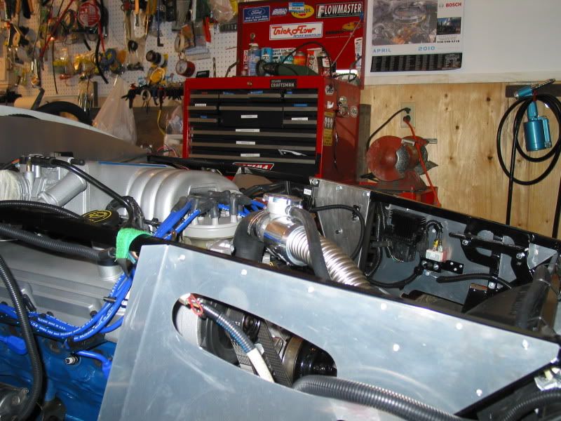
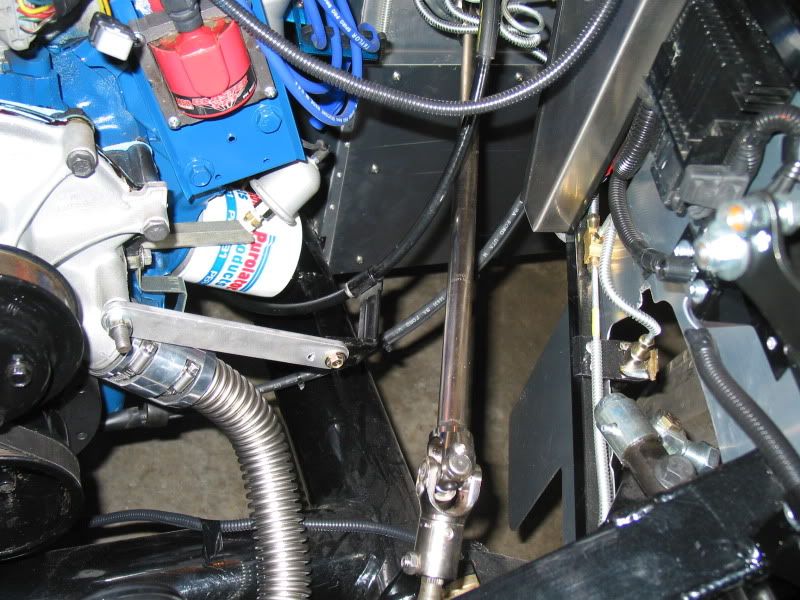
With that job done I have to start looking at how I am going to mount my air intake hose, and MASS air sensor. There is space for it, and the K&N cone style filter that is included in the kit, but I will likely need to make a custom bracket to hold it in place. I just can't figure out how to use the stock MASS air bracket and hose to hold things clear of the headers, wire harnessss etc.
I have seen some pretty sharp looking aftermarket cold air intake set ups, for the 5.0 engine, and may investigate these. They would look better than the OEM stock black rubber hose, and may allow me more options for mounting my filter. Any suggestions as to make, and/or suppliers for these?? I can't afford to spend a fortune, so preferably it is a reasonably priced set up. (It would be nice, if it was adaptable to a larger throttle body, as I may be able to use it then with my Trick Flow Street Burner intake system, when I eventually install it)
I will install my passenger side header first. This will allow for correct postioning of the air intake, as well as allow me access to tighten up the header bolts without interference.
This is the space I have to fit the intake into.

. I am using the Powermaster XS high torque mini starter, that came with the donor parts. I don't know why the previous owner of the Mustang GT had this starter, but I figure the factory Ford one must have failed at some point, so he opted for one of these to replace it. They are more commonly used on engines that have been " warmed over" a bit. It's ok with me, as it is smaller and lighter than the OEM one.
As I still have used a stock FOX type remote starter solenoid, I needed to wire the starter in such a way as to prevent starter "run on" which apparently is quite common for this style aftermarket starters. The fellows that have had these issues, usually use a jump wire between the smaller starters solenoid post, and the larger +12V post. This engages the starters solenoid when the key is turned on, and the stock remote solenoid sends power down the main power cable. Some speculate that the starter spinning actually creates an electrical feedback that keeps the starters solenoid triggered, thus inducing the "run on" problem.
You could wire the battery cable and ignition start wire directly to the starter, without using a stock type remote starter solenoid at all. This would eliminate the run on issue. Many builders do it this way.
In my case, as with other builders, we need to use the remote solenoid to attach several other items that require +12V power. Using the donor wire harness's, this is common because of the harness routing, leading to the area that the remote solenoid is normally mounted in the Mustang (79-93 years at least).
To wire the mini starter using the remote solenoid, I ran the
stock donor heavy gauge cable from the "always hot" side of the remote solenoid, to the large post on the starter. I then ran a 10 Ga wire, from the other post on the remote solenoid, (that is "triggered" when the ignition switch is turned on) to the smaller post on the starter, to engage it's built in solenoid.
I used the wire routing for both cable and 10 Ga wire, the same way as the stock Mustang configuration. This makes use of the two brackets that attach to the lower front of the engine, designed to keep the wires clear of the front crank pulley, and headers. I simply zip tied the smaller wire where needed to the larger cable, or fed it through the cable's loom cover, at the front of the engine. I gather that Ford only used a loom cover in this area, to protect the harness from road debris?
With that job done I have to start looking at how I am going to mount my air intake hose, and MASS air sensor. There is space for it, and the K&N cone style filter that is included in the kit, but I will likely need to make a custom bracket to hold it in place. I just can't figure out how to use the stock MASS air bracket and hose to hold things clear of the headers, wire harnessss etc.
I have seen some pretty sharp looking aftermarket cold air intake set ups, for the 5.0 engine, and may investigate these. They would look better than the OEM stock black rubber hose, and may allow me more options for mounting my filter. Any suggestions as to make, and/or suppliers for these?? I can't afford to spend a fortune, so preferably it is a reasonably priced set up. (It would be nice, if it was adaptable to a larger throttle body, as I may be able to use it then with my Trick Flow Street Burner intake system, when I eventually install it)
I will install my passenger side header first. This will allow for correct postioning of the air intake, as well as allow me access to tighten up the header bolts without interference.
This is the space I have to fit the intake into.
AC Bill
Well-known member
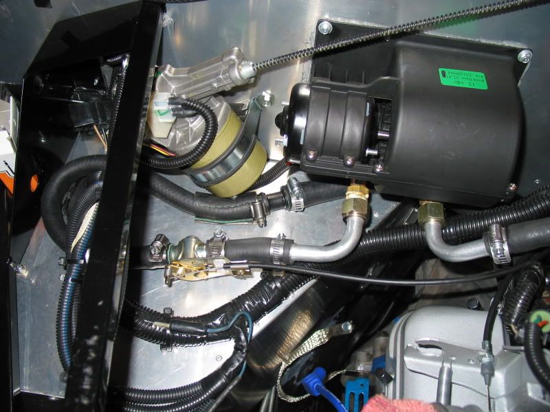
HEATER HOSES
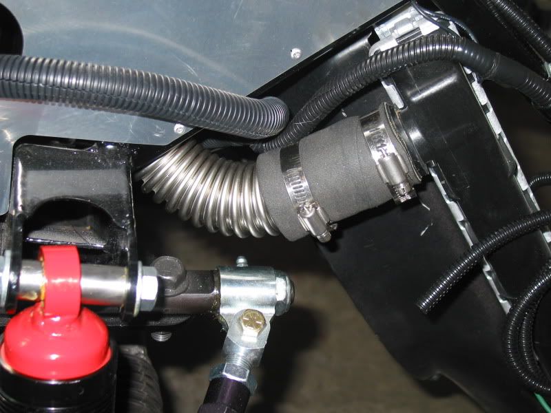
I have managed to find a way to hook up the heater water hoses to the awkward Vintage make heater inlet/outlets. The stock 5.0 engine has two different size heater pipes at the back to of the intake manifold. The Vintage heater has both in/out pipes the same size. As well the Vintage heater has the in/out pipes, on a 90* bend. The OEM Mustang heater hoses at this point were useless, although nicely molded.
I thought initially perhaps I could find some aftermarket molded heater hoses to suit, but this seemed near impossible. Fortunately I found an adapter that allowed me to join the required smaller hose off the heater outlet, to the larger pipe on the engine. This was a huge bonus and made the job a lot less confusing then I thought it was going to be. I had visions of having to solder copper step down pipes etc..
I simply bought some lengths of the different size heater hose that I needed, and then tried fitting them in behind the engine as best I could. You need fairly wide bends in the hose to prevent them from kinking, unlike pre-molded hose, so I had to use longer hose lengths, and route them to allow for these bends..Not the prettiest set up in the world, but this will be mostly hidden under the cowling at the back of the hood.
A big thanks is owed to my great friend Larry, for his help in this, as well as many areas of my build so far. He has been a huge fan of the Cobra's and really wants to see this car on the road as much as I do.
In this picture you can see the water control valve that is provided with the heater. This also requires some thinking as to positioning, as the control cable leading to it requires smooth arcs, to prevent binding issues. Also seen is the step down adapter, which made this job much easier.
HEATER HOSE INSTALLED
I also have found a postion for the O2 sensors to be mounted to my headers, so I took the threaded bungs and the headers to a welder to get the bungs welded on. One of the donor O2 sensors was in really rough shape so I decided rather than taking a chance on it, to replce it with a new one. Bloody expensive little things!
I decided to wait to do the final routing of the 02 harness until the headers are on, and I can see how much play I have on the harness.
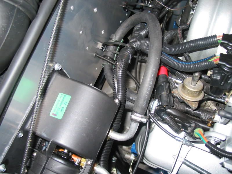
I bought some DEI heat wrap, to cover my battery positive cable that runs along the frame above the headers. (as seen in earlier photos) I was warned that this area could get pretty hot, and melting of the cable could lead to some serious shorting under the hood..hmm sure don't want that.
CABLE INSULATION
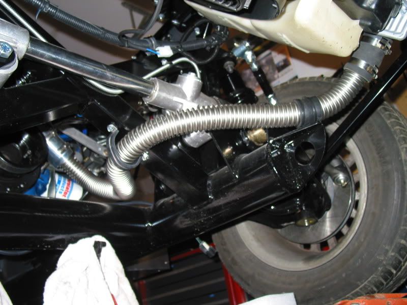
I also managed to install the lower rad hose. I used the supplied stainless hose, and the hose couplers supplied in the kit. I worried that it may hang fairly low, so I modified a large padded wire harness clamp, and fastened the hose to the frame, just to be safe. I also zip tied a piece of rubber hose where the hose touched the frame, to prevent wear through. The stainless hose is pretty tough compared to a rubber rad hose, but better be safe than sorry.
LOWER RADIATOR HOSE INSTALLED
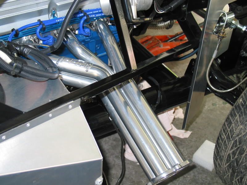
After reading of problems some builders had with their clutch cables melting from being to close to the headers, I devised a very simple aluminum bracket to hold my cable in place, well away from the heat. This allos allows a smooth arc in the cable, to help prevent any potential for cable binding. The OEM cable bracket was simply bolted to this aluminum bracket.
I have managed to find a way to hook up the heater water hoses to the awkward Vintage make heater inlet/outlets. The stock 5.0 engine has two different size heater pipes at the back to of the intake manifold. The Vintage heater has both in/out pipes the same size. As well the Vintage heater has the in/out pipes, on a 90* bend. The OEM Mustang heater hoses at this point were useless, although nicely molded.
I thought initially perhaps I could find some aftermarket molded heater hoses to suit, but this seemed near impossible. Fortunately I found an adapter that allowed me to join the required smaller hose off the heater outlet, to the larger pipe on the engine. This was a huge bonus and made the job a lot less confusing then I thought it was going to be. I had visions of having to solder copper step down pipes etc..
I simply bought some lengths of the different size heater hose that I needed, and then tried fitting them in behind the engine as best I could. You need fairly wide bends in the hose to prevent them from kinking, unlike pre-molded hose, so I had to use longer hose lengths, and route them to allow for these bends..Not the prettiest set up in the world, but this will be mostly hidden under the cowling at the back of the hood.
A big thanks is owed to my great friend Larry, for his help in this, as well as many areas of my build so far. He has been a huge fan of the Cobra's and really wants to see this car on the road as much as I do.
In this picture you can see the water control valve that is provided with the heater. This also requires some thinking as to positioning, as the control cable leading to it requires smooth arcs, to prevent binding issues. Also seen is the step down adapter, which made this job much easier.
HEATER HOSE INSTALLED
I also have found a postion for the O2 sensors to be mounted to my headers, so I took the threaded bungs and the headers to a welder to get the bungs welded on. One of the donor O2 sensors was in really rough shape so I decided rather than taking a chance on it, to replce it with a new one. Bloody expensive little things!
I decided to wait to do the final routing of the 02 harness until the headers are on, and I can see how much play I have on the harness.
I bought some DEI heat wrap, to cover my battery positive cable that runs along the frame above the headers. (as seen in earlier photos) I was warned that this area could get pretty hot, and melting of the cable could lead to some serious shorting under the hood..hmm sure don't want that.
CABLE INSULATION
I also managed to install the lower rad hose. I used the supplied stainless hose, and the hose couplers supplied in the kit. I worried that it may hang fairly low, so I modified a large padded wire harness clamp, and fastened the hose to the frame, just to be safe. I also zip tied a piece of rubber hose where the hose touched the frame, to prevent wear through. The stainless hose is pretty tough compared to a rubber rad hose, but better be safe than sorry.
LOWER RADIATOR HOSE INSTALLED
After reading of problems some builders had with their clutch cables melting from being to close to the headers, I devised a very simple aluminum bracket to hold my cable in place, well away from the heat. This allos allows a smooth arc in the cable, to help prevent any potential for cable binding. The OEM cable bracket was simply bolted to this aluminum bracket.
AC Bill
Well-known member
CLUTCH CABLE BRACKET
Some more progress this weekend!
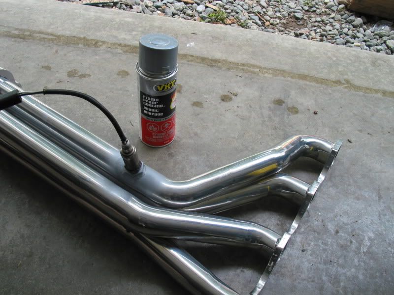
I rec'd the headers back after getting the 02 sensor bungs welded in place. The fellow did a nice job, and used anti-splatter spray on them so they came back clean, and with no damage to their ceramic coating. I used VHT spray paint to touch up the bung and the weld to prevent rust.
02 BUNG WELDED TO HEADER
I then proceeded to put the headers on the engine. The Percy split lock header bolts I used, first needed a coat of anti-seize on both the bolt and the pin that locks the bolt into the head. The flange on the BBK header and the thickness of the Remflex gasket had me nervous for a bit, as it initially looked like the bolts may be to short. I did manage to get them in finger tight, before using a 12 point 3/8" closed end wrench to tighten them up. Only a 12 point wrench will work on these. There is not enough room for a regular socket wrench. According to Remflex info the bolts are only tightened to about 15 ft/lbs, and the gasket compressed about 50%, so a wrench like this worked well. After the bolts were in, I tightened up the small Allan head pin that expands the bolt, to lock it in. They require only approx 7 ft/lbs. I could only really do this by feel, as I have no room to use a torque wrench in this confined space.
As so often happens during the build, once I had the headers all tightened up, I realized I still had to re-install the oil dipstick tube, and fasten it. (The tube needs to be removed from the block to be able install the headers). Of course it uses a header bolt to fasten the tubes upper brace, so .....get the wrench, and Allan key back out..
I have heard of some builders having problems with their dip stick tube leaking where it enters the block after a re-install. The tube is tapered at this point, and took a bit of tapping to re-insert it, but to be safe, I used a small bead of Seal-All on the tube.
Once the headers were all on I was able to install the plug lead loom holders to the valve cover bolts, and slip the leads onto the plugs. I used some dielectric grease as recommended, applied with a Q-tip, on both the cap and plug ends of the leads. This is supposed to make it easier to remove the leads in future, as well as provide corrosion protection.
HEADERS INSTALLED
I had installed the 02 sensors in header pipes #4 and #8. I know this is not the best way to get a good overall reading from the sensor to the computer, but is very common on these builds. The reason is that the sensors would have to be installed in the collector in the side-pipe to get an overall reading from each bank of cylinders. That location has been known with some to not be hot enough for the sensor to read accurately.
As well they can be awkward to install, and a bit unsightly on the side-pipes.
So I moved on with the final routing of the 02 sensor harness, and fastened it to the frame. Most of the holes for the harness clips could be drilled from above, but I had to get under the car on a creeper to drill and fasten a couple of them. I didn't want the harness connectors rattling around so I zip tied these in place as well.
02 HARNESS INSTALLED
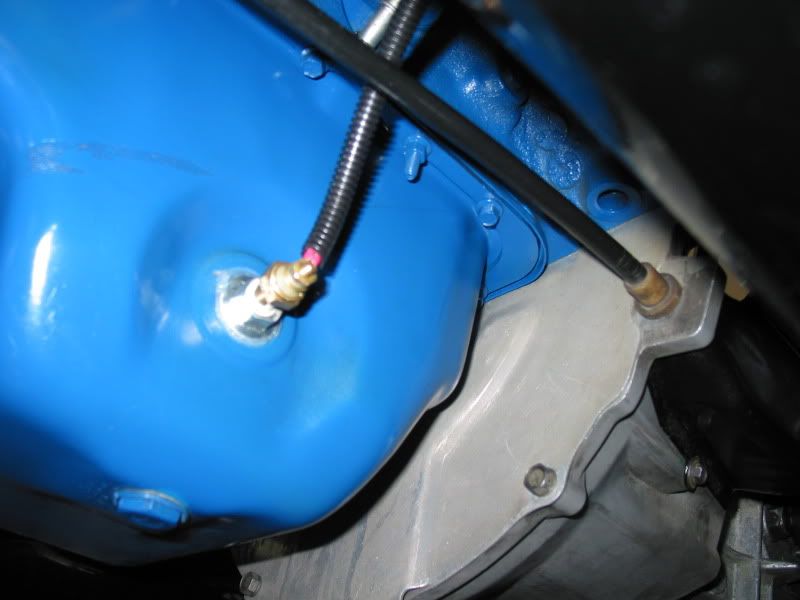
Since I was under the car, I decided to attach the harness for the oil temperature sender, which was installed in the oil pan. Most of the Fox owners would see a low oil sensor in this position. I removed the stock sensor, and my friend Larry drilled and tapped a drain plug that was the correct size for this threaded hole in the pan which the temp sender was then in turn threaded into.
OIL TEMP SENDER
Some more progress this weekend!
I rec'd the headers back after getting the 02 sensor bungs welded in place. The fellow did a nice job, and used anti-splatter spray on them so they came back clean, and with no damage to their ceramic coating. I used VHT spray paint to touch up the bung and the weld to prevent rust.
02 BUNG WELDED TO HEADER
I then proceeded to put the headers on the engine. The Percy split lock header bolts I used, first needed a coat of anti-seize on both the bolt and the pin that locks the bolt into the head. The flange on the BBK header and the thickness of the Remflex gasket had me nervous for a bit, as it initially looked like the bolts may be to short. I did manage to get them in finger tight, before using a 12 point 3/8" closed end wrench to tighten them up. Only a 12 point wrench will work on these. There is not enough room for a regular socket wrench. According to Remflex info the bolts are only tightened to about 15 ft/lbs, and the gasket compressed about 50%, so a wrench like this worked well. After the bolts were in, I tightened up the small Allan head pin that expands the bolt, to lock it in. They require only approx 7 ft/lbs. I could only really do this by feel, as I have no room to use a torque wrench in this confined space.
As so often happens during the build, once I had the headers all tightened up, I realized I still had to re-install the oil dipstick tube, and fasten it. (The tube needs to be removed from the block to be able install the headers). Of course it uses a header bolt to fasten the tubes upper brace, so .....get the wrench, and Allan key back out..
I have heard of some builders having problems with their dip stick tube leaking where it enters the block after a re-install. The tube is tapered at this point, and took a bit of tapping to re-insert it, but to be safe, I used a small bead of Seal-All on the tube.
Once the headers were all on I was able to install the plug lead loom holders to the valve cover bolts, and slip the leads onto the plugs. I used some dielectric grease as recommended, applied with a Q-tip, on both the cap and plug ends of the leads. This is supposed to make it easier to remove the leads in future, as well as provide corrosion protection.
HEADERS INSTALLED
I had installed the 02 sensors in header pipes #4 and #8. I know this is not the best way to get a good overall reading from the sensor to the computer, but is very common on these builds. The reason is that the sensors would have to be installed in the collector in the side-pipe to get an overall reading from each bank of cylinders. That location has been known with some to not be hot enough for the sensor to read accurately.
As well they can be awkward to install, and a bit unsightly on the side-pipes.
So I moved on with the final routing of the 02 sensor harness, and fastened it to the frame. Most of the holes for the harness clips could be drilled from above, but I had to get under the car on a creeper to drill and fasten a couple of them. I didn't want the harness connectors rattling around so I zip tied these in place as well.
02 HARNESS INSTALLED
Since I was under the car, I decided to attach the harness for the oil temperature sender, which was installed in the oil pan. Most of the Fox owners would see a low oil sensor in this position. I removed the stock sensor, and my friend Larry drilled and tapped a drain plug that was the correct size for this threaded hole in the pan which the temp sender was then in turn threaded into.
OIL TEMP SENDER
AC Bill
Well-known member
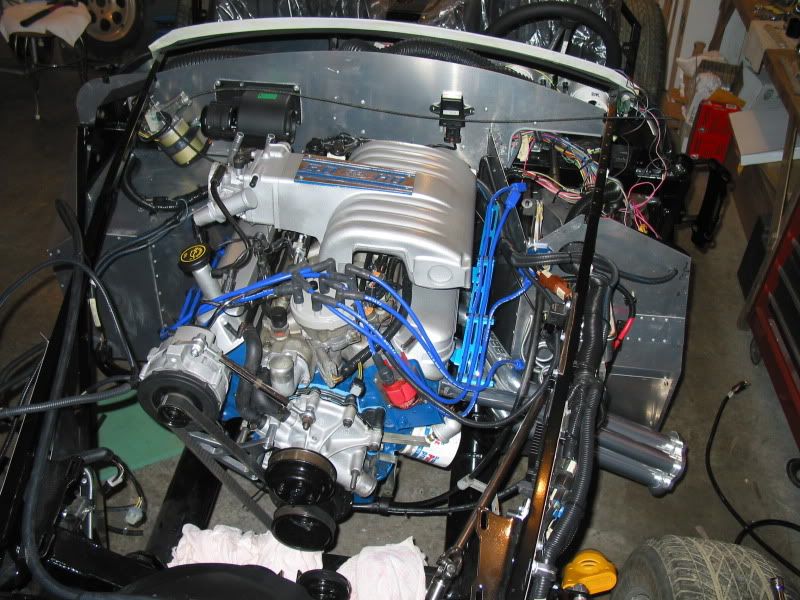
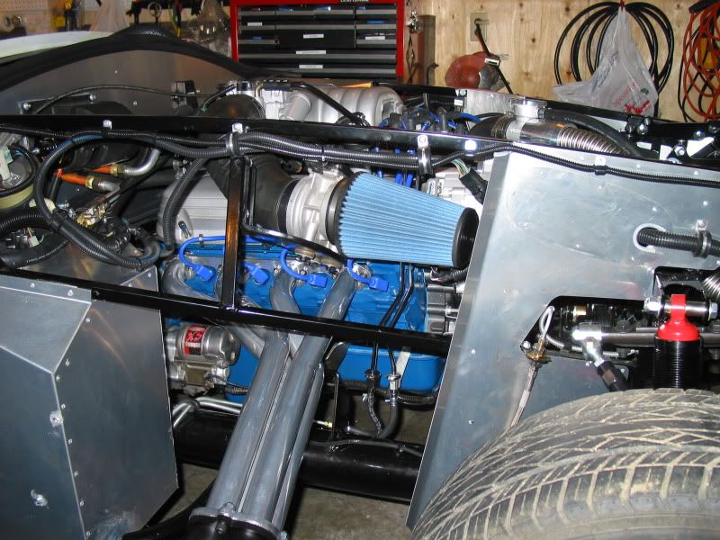
The manual, for a change, did make the mounting of the MAF, intake, and supplied K&N filter pretty straight forward. I was humming and hawing about getting a performance cold air intake set up, but was anxious to get things hooked up and ready for a first start. (I figured this would be a pretty simple add on at a later point). I was able to use the stock Fox MASS air set up, and simply had to drill a couple of holes in the frame to match up with the mounting holes on the stock bracket. The K&N cone type filter replaces the stock filter. There is simply no room for a stock filter box under the hood in this car.
MASS AIR
After a check to make sure all the engine electrical was plugged in, and everything else looked good, we added oil, and coolant to the engine. Since I don't have a new battery, I charged up my boat battery for an hour or so, and hooked up the battery cables to it. Starting with the simple stuff, we tested the horn. It worked good and loud! My dog was not impressed mind you, as we woke him up from his shop bed, that he likes to snooze in when I am working in the shop.
I turned the key to the on position, and tested the wipers, heater fan, and radiator cooling fan's manual override switch. All worked great, and the cooling fan was blowing in the right direction..bonus! Since non of the lights are hooked up we couldn't test them or the signals. My foot box lights worked good though.
The next step was to climb in, check the car was in neutral, and crank the engine over a few times. The coil lead was pulled, as was the fuel pump inertia switch connector, as I didn't want to actually start it, but just to pump up the oil pressure a bit, as well there is no gas in the tank, so I didn't want the fuel pump running. She cranked over just fine, so I know the starter was wired properly..
The next step is to put some gas in the tank, and see if it will fire up. I want to do this outside the shop, just in case there is a gas leak, or fire, or the engine explodes, etc..Note, I will keep a good extinguisher on hand...just in case..
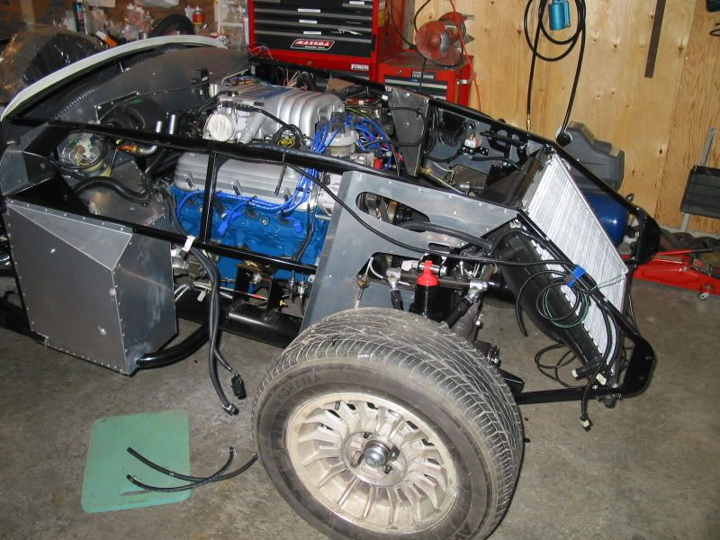
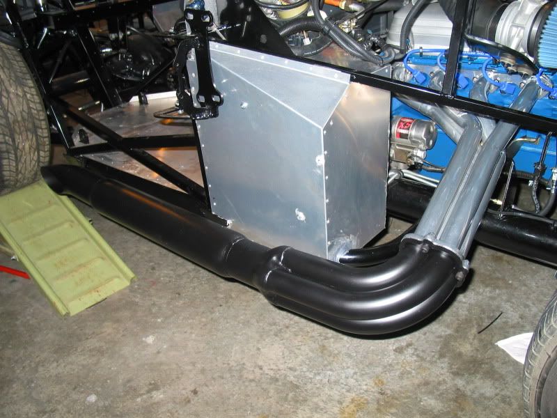
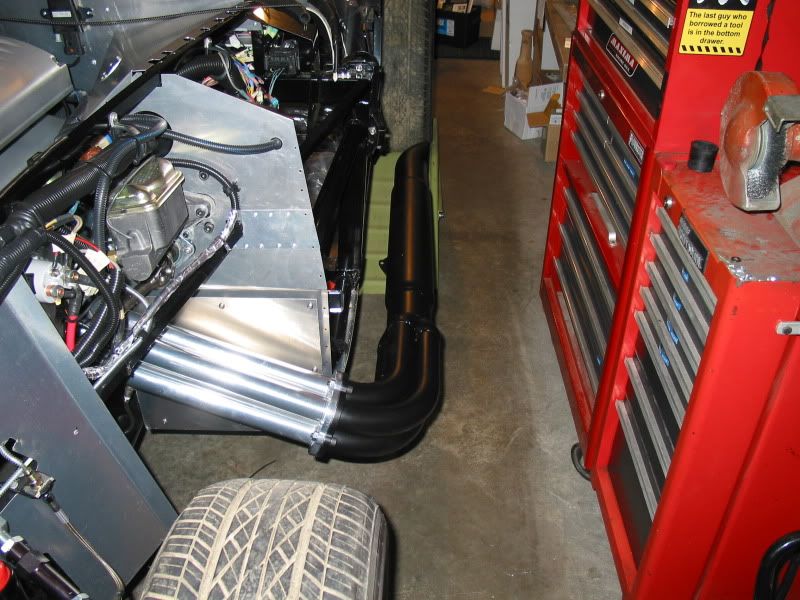
I lied..Actually the next step was to install the side pipes. I wanted to check them for fit. I also thought they may help a bit in not freaking out the neighbors, when/if the engine starts for the first time..
I used Plastcoat BBQ paint on them that I picked up at Lordco. Apparently this is the best stuff to use if you don't have access to a industrial oven to be able to bake them. Some of the header coatings require baking at 650*F for 60 minutes. They will need touch ups from time to time from what I hear from other builders. I thought they turned out pretty good.
SIDE PIPES
MASS AIR
After a check to make sure all the engine electrical was plugged in, and everything else looked good, we added oil, and coolant to the engine. Since I don't have a new battery, I charged up my boat battery for an hour or so, and hooked up the battery cables to it. Starting with the simple stuff, we tested the horn. It worked good and loud! My dog was not impressed mind you, as we woke him up from his shop bed, that he likes to snooze in when I am working in the shop.
I turned the key to the on position, and tested the wipers, heater fan, and radiator cooling fan's manual override switch. All worked great, and the cooling fan was blowing in the right direction..bonus! Since non of the lights are hooked up we couldn't test them or the signals. My foot box lights worked good though.
The next step was to climb in, check the car was in neutral, and crank the engine over a few times. The coil lead was pulled, as was the fuel pump inertia switch connector, as I didn't want to actually start it, but just to pump up the oil pressure a bit, as well there is no gas in the tank, so I didn't want the fuel pump running. She cranked over just fine, so I know the starter was wired properly..
The next step is to put some gas in the tank, and see if it will fire up. I want to do this outside the shop, just in case there is a gas leak, or fire, or the engine explodes, etc..Note, I will keep a good extinguisher on hand...just in case..
I lied..Actually the next step was to install the side pipes. I wanted to check them for fit. I also thought they may help a bit in not freaking out the neighbors, when/if the engine starts for the first time..
I used Plastcoat BBQ paint on them that I picked up at Lordco. Apparently this is the best stuff to use if you don't have access to a industrial oven to be able to bake them. Some of the header coatings require baking at 650*F for 60 minutes. They will need touch ups from time to time from what I hear from other builders. I thought they turned out pretty good.
SIDE PIPES
AC Bill
Well-known member
The main thing is having the patience to try not to rush the build. Another builder once said, "There is nothing that you can't un-do, and re-do, on these cars". I believe that is true, but, if you can try to learn the best way to do things the first time round, it could save a heck of a lot of frustration for you.
Having the patience to do a lot of research, prior to fastening the first rivet, or tightening the first bolt helps tremendously in the long run. I have read and re-read the FFR manual, to get a broad prospective on the job, as well I have a factory Ford service manual, and a Clymer manual, that gives me many of the needed small details. As I mentioned previously, the FFR builders web forum has been my main source of education, on so many areas of the build.
It should also be expected there are times that you need to step away from the building process, and come back at it later with a fresh mind. You can't let the frustrations (that at some point in your build process, that your bound to run in to), get the best of you.
For instance, I had been working on a unique idea for a foot box cooling system, as like the originals, these cars are known to get pretty warm in this area. I had this elaborate plan all figured out, bought the needed items, and started into the plan. It wasn't long when I came to the realization that the blower fan I had bought, just couldn't push the air fast enough, or enough volume of air, to really be effective.
Now this sucked, as my plans were done completely around this blower I had bought..
Two months later I am currently working on a new plan with a new blower that will be far better than the original idea. This blower has four speeds, where the original had only one. It also pushes about 10 times more the volume of air. When it all comes together, it should be really impressive. I'll discuss this all here at some point.
My main point is, that patience, and being able to step away once in awhile, is as important as your mechanical skills..

AC Bill
Well-known member
It was a huge challenge, but the ultimate reward that you would obtain in the end, keeps driving you to overcome the hard things, and keep you moving on the project. I've had Cobra's in my blood since I was a little kid, so for me, it was fulfilling a dream. Many fellows that may not have the Cobra bug as bad as I do, could be flummoxed at some point, and simply give up. I'm also thankful I chose the FFR Roadster, over other replicas.
Factory Five Racing, unlike most of the other replica manufactures that have appeared, and disappeared over the years, have put together a well engineered product, that "can" be built to a successful completion. I'm sure there is at least a dozen, (probably more), Cobra replica's, of varying makes, in Canada, just sitting in garages gathering dust. More than likely it was a very poorly designed kit that required a builder to have a degree in automotive engineering to work around the design flaws. Some of them required a builder to use donor parts from three, four, or even more different donor cars. An Jaguar E-type rear end, an MGB, or a Mustang II front suspension, a Chevy or even a Rover V8 engine,a fuel tank from a 56 Edsel, steering wheel from a 79 Fiat.. sort of thing..lol
With Factory Five Racing, you need one car only, a Mustang, And not just one or two specific model years, but pretty well any V8 models from 1987 to current. I think that has been the key to their success for over 20 years now.., and the reason they are #1 in the replica industry today.
Although a builder is not limited to using a Mustang as a donor, certainly enough FFR's out there running big blocks, independent rear suspensions, Wilwood brakes,, etc.,