I touched on the wire harness aspect of the build, but of course there is still a lot of wiring. Some of the items that need to be joined up to the wire harness are done towards the completion of the build, as the body need to be on. Headlights, taillights, turn signals, back up lights, and license plate light, can all be tested with the body off, but final connections are all done after the body is on. Other wiring that can still be completed includes the horns, electric fan, (which comes with the kit), stereo if you choose, e-brake warning light, and switch, and the dash.
The dash I still have to do yet, but as I opted to use aftermarket instrumentation, and switches, you pretty well start from square one. All the senders, need to be wired back to the dash from the engine, which will include oil pressure, oil, and water temperature. In addition I need to wire up the tach, and speedo. The gauges I chose are all electric, so they hopefully will be pretty straight forward. The speedo comes with a module to allow you to calibrate it for the gears, and tire diameter you are using.You can use the donor VSS on the tranny, but need to plug the cable drive hole in it first. The newer style Mustangs don't use a cable drive, so you can choose to use one of these instead. The gauge lights will all need to be wired as well for night driving. The dash is basically wired off the car, and then temporarily fastened to the dash hoop, and connected to the chassis, and engine wiring, for testing. It generally is not permanently mounted till after the body is on. This is because the top edge of it has to tuck up under the body cowl, and you don't want the body actually resting on it.
NOTE- You can choose to use the donor gauge cluster, and several switch's from the Mustang. Headlight, ignition, dash dimmer, even turn signal switch's can all be used. This can be a real money saver, and the final result is actually pretty good, and very functional. The kit includes round bezels and glass for the gauges to go behind, after cutting them from the cluster, The manual covers this procedure in pretty good detail.
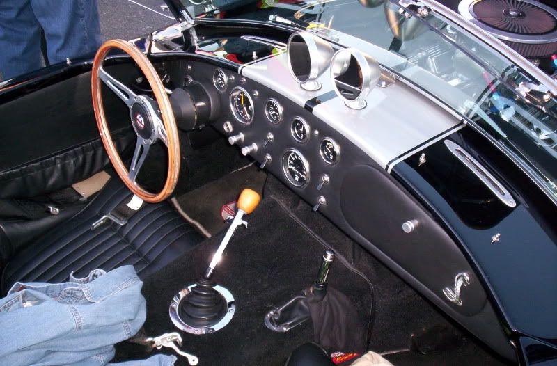
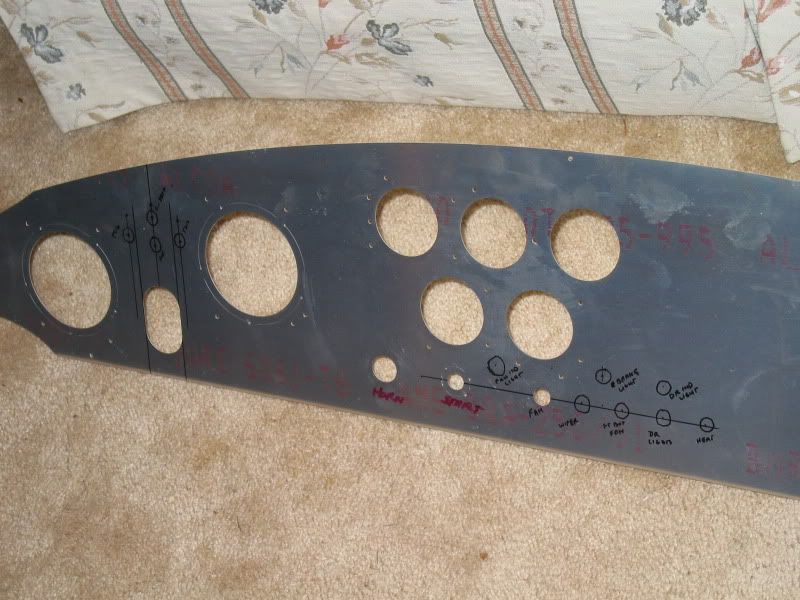
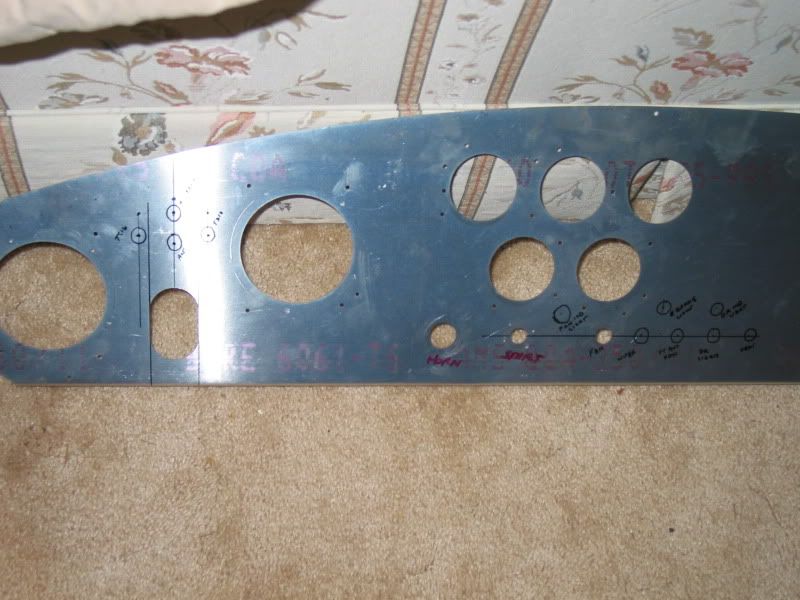
There are two styles of dash that you can choose depending on the layout you prefer. The standard dash that comes with the kit is all precut for gauges, and a few switch's, in the traditional Cobra 427S/C style. Some will choose the optional Cobra Competition dash layout, or you can even order a blank dash, cut your own holes, and lay it out however you want. Here is one example of a custom dash layout.
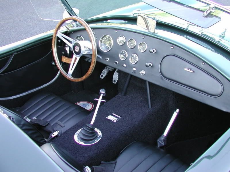
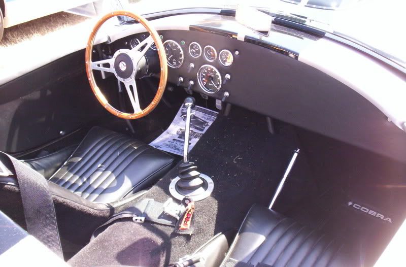
Here is the traditional 427S/C dash layout, that come with the kit.
WIPERS and HEATER
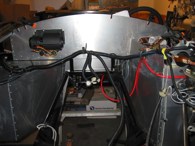
I chose the optional heater, and wipers so they also need to be wired. The heater I have installed in the firewall. It's a compact little 3 speed unit, and comes with defrost and footbox ducting, as well as defrost bezels for the dash cowl, and controllable ball type vents for the footbox's. There is no flap, or flap control to choose which area you want hot air to go to. Basically if you want more air on the windshield, you turn off the footbox vents. I guess if you want more hot air in the footbox areas, you need to put a book or something on the defrost outlets.
, as they are not controllable. The single switch that comes with the heater, controls the fan speed, and the cable controlled water valve, to increase/decrease heat. It's a simple pull/push control knob, that you can also turn to select blower speed. Heater Installed (Note, defrost bezels can be seen on dash photos above)
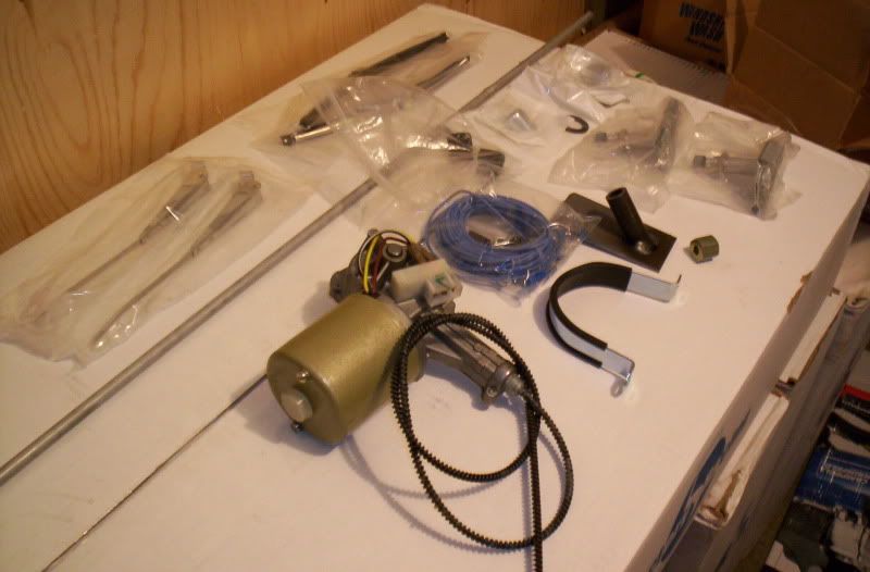
The wiper motor, and drive system is very much the traditional British Lucas style, as found on the sixties style MG's, Triumphs, and Cobras, etc. It is not a joy to install the drive system from what I have heard. The motor install and wiring itself is not a big deal though. It's designed to be mounted to the firewall, on the passenger side next to the heater. The switch is a simple two speed toggle switch. Apparently some fellows have figured out how to wire a park/return feature, but the instructions that come with it don't show this. I guess you have to time them just right, to shut them off at the bottom of the stroke otherwise. lol . Other builders say they do work at what they are supposed to do, but in reality you don't want to be caught in a situation where they are needed. A weather satellite receiver would probably be more practical, but you need wipers to pass the inspection.so...(Some Provinces, or certain US states, may not require wipers to pass inspection) WIPER KIT
The FFR manual has you mounting the battery in the trunk of the vehicle.
Different strokes for different folks, when it comes to this aspect of the build. Some builder have chosen to mount the battery up front, using either a custom built support, or a commercially available one. They usually mount them just in front of the engine, down low. As there is no spinning mechanical fan, (as on the Fox Mustang) there is room here for it. The usual advantage's claimed in mounting it here are; Easy to reach if jumping it (access), shorter cables (less resistance), and weight distribution.
The trunk mounting on the new model (MKIII 3.1) as per FFR, is to mount it on the floor of the lower trunk area. A plastic battery box with lid, and all hold down hardware is all included in the kit for this. You also receive a positive battery cable long enough to reach the front starter solenoid.
Some builders have chosen to do a battery trunk box drop modification. The battery sits below the trunk floor, above the fuel tank, in a custom made box, or a commercially made one, designed for the Roadster. An access panel is left in the trunk floor. This gives one more trunk space, and perhaps a tidier look, if showing the car.
I went with the standard layout as per the manual. It is easy to install, and easy access for charging or jumping. I do lose some trunk space, but I won't likely be hauling around much more than two lawn chairs, a sweater/jacket, small tool kit, jack, and maybe a donut type spare tire. NOTE;The spare tire is considered an option with these cars, mainly because once you remove the full size tire, where do you put it?
The reason being that the meatier tires builders tend to put on these cars, for both cool looks, and needed traction, won;t easily fit in the trunk! If your by yourself you could put it in the passenger seat, but what if you have a passenger? I suppose you could ditch the tire in some bush's, or leave it with someone, and pick it up later. You could also become a member of an Automobile Assoc. and have the car flat decked home, (as a regular tow truck won't cut it, with this low road clearance car). Many builders choose to carry some of those flat tire inflater/sealer cans instead of a spare. Depending on the reason for the flat, I suppose this may be a good choice.
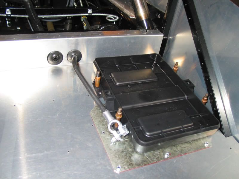
Battery tray, and cable installed.
NOTE The panel under the battery tray, is one of two that I installed in the trunk floor, above the fuel tank, for access panels to the pump, and fuel level sender, should I ever need to replace them. Beats dropping the tank to do this. They will have carpet over them eventually, so won't be so evident.
I used PCV valve cover grommets to run both cables through, as you don't want the sharp aluminum cutting into them. They are the perfect size! I ran my negative cable to a keyed master shut off switch, so I can cut all power to the car, for a theft detterent, while working on the car, or for an emergency shut down. I mounted the switch in the cockpit, at the rear of the centre console, between the seats for easy access.
RADIATOR INSTALL
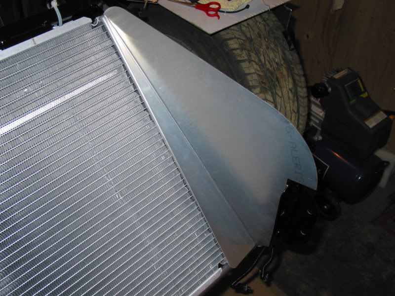
The manual shows you how to install the donor Mustang radiator, and overflow bottle. Some choose to use a new radiator, (as I did), some choose an optional custom made one designed for this car. A lot depends on your engine selection, or how souped up your engine is. I chose a replacement Mustang Performance rad. This has the dimensions of the stock rad, but is an all aluminum core, which is considerably lighter weight. You can use the donor overflow bottle, or buy a new generic one, and mount it in the engine compartment. Just make sure you get one that is large enough.
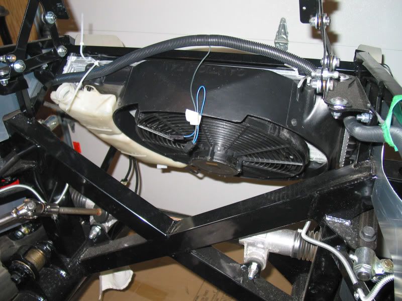
The stock fan shroud can be used, on which the supplied electric fan is mounted. All the hardare for mounting, and wiring the fan, comes with the kit, including the switch,and relay. It's actually a pretty simple job. I cleaned my donor shroud, and the painted it using the SEM product made for painting plastic/fibreglass, just to spruce it up a bit. The SEM prep is great stuff, and you should use it before applying the final finish coat. (I also used these products on my fuel tank lower plastic cover)
I didn't care for the method that FFR called for in the manual, to mount the rad. It seemed rather a lame way to do it, and I felt the rad wouldn't be supported properly, with stress in some areas. Reading threads on the builders forum, kind of confirmed it was less than satisfactory. Many have done it by the book though, and seem happy..so your choice.
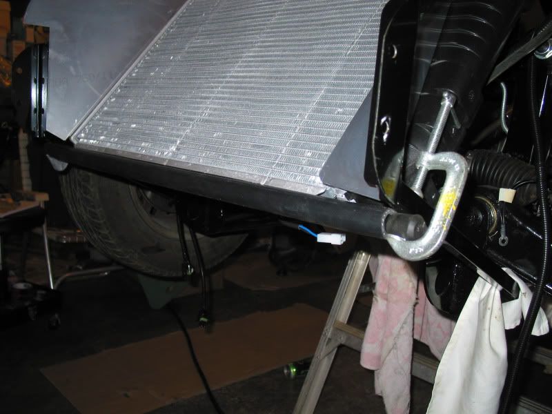
I made a lower rad support made from a pipe, that I slipped some rubber hose over, to prevent metal to metal contact. This pipe was than attached to the frame using some brackets. I covered the ends of the exposed pipe, with walking cane tips. (you have to be inventive, lol). Radiator lower support.
The air flow is directed by side, and bottom aluminum panels, that are installed after the body is on. These are riveted to the frame of the car. Side aluminum panel
MORE WIRING
One of the most difficult things I have done so far, is trying to route and mount the wiring harness. The problem is mainly in the engine compartment, because the engine isn't in yet, it's hard to visualize what your clearances are from extreme heat sources, and also if the connectors will reach their intended targets. For example; the connectors to to the salt and pepper shakers at the back of the plenum, alternator connectors, distributor connectors, etc.. I could have waited till the engine was in, but there isn't a lot of room then to get the drill in, for drilling harness retainer mounting holes.
Much of the harness is held to the frame with rubber coated harness holders, that I have riveted on permanently. They are available in several sizes and actually look and work pretty good. In other areas I have used these black plastic zip tie holders. You screw or rivet them on, then run a zip tie through it, and then around the section of harness you are trying to secure. The nice thing about these is that if I find the harness won't quite reach a connection point, I should be able to simply cut the zip tie, and add a longer one that will give the harness more slack. Or if it's really out of position, I can simply unscrew it, relocate it, and fill the unused hole with a rivet.
The other part of wire harness routing, is to try and keep things looking good by hiding as much of the harness as you can. This can be tricky as you only have so much length to work with, so no matter what some of it will be exposed. I have added new plastic spiral loom covers to the majority of exposed harness, so that should help.
I am using the remote starter solenoid, that is common to the Mustang, and it has a lot of wires running to it. Initially I mounted it to an additional stainless steel panel I made. With the solenoid in the engine compartment, it looked rather busy with wires, so I simply put the switch on the backside of this panel. If I need to access it, I can simply unbolt the stainless panel from the frame.
The Daytime running light module, and the electric cooling fan relay, I will mount in the engine bay. I also will have the BAP sensor mounted on the firewall.
HORNS
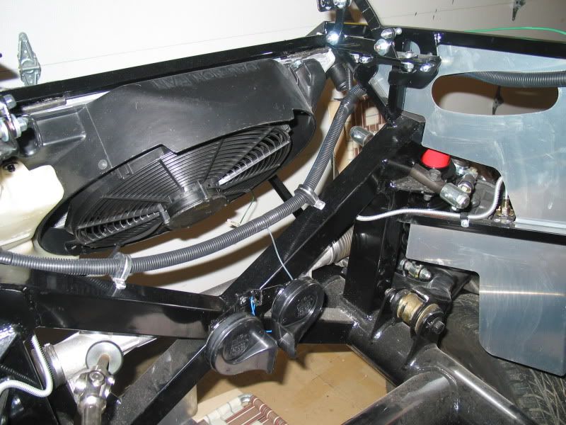
I looked at several different spots to mount the horns, and finally decided on a spot close to the front, behind the rad. I had to make a custom bracket to hold them. I hope they will still be loud! The custom steering wheels, of which I have a original style wood one, and a performance style leather one, to choose from, have no center horn button, so a simple dash mounted push button switch will be used. The horns are from the Mustang, although I'm not sure if they are stock or not. The push button horn switch is supplied in the kit. I need to mount this button within easy reach of the steering wheel, and shifter.
ECM MOUNTING
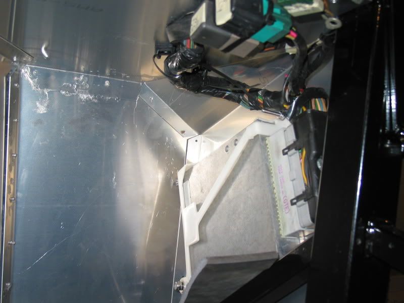
The FFR manual calls for you to mount the ECM on the underside of the passenger footbox top. The large wire harness that runs to it is supposed to be run through the passenger side firewall. Initially I mounted it there, and ran the harness as per instructions, but I really didn't like the look of this large harness protruding beneath the dash. I did a little brainstorming, and decided to mount the ECM in a similar location to the Mustang, down in the right kick-panel area. I also re-routed the harness through the top of the footbox, rather than the firewall, so it is hidden.
Being that the ECM mounted in this position, may be vulnerable to the odd kick from a passenger, I had to design a inner kick panel to protect it. This kick panel will eventually be covered in carpet, so I wasn't to worried about the look. Initially I thought of an aluminum baking tray...you know those flat sheets your Mom made cookies on..I went down to the local Sally Ann, thinking that might be the place to find one cheap. Well I didn't find a baking tray suitable, but I did find this aluminum serving platter. It had this fluting around the edge, and was nicely engraved with some flower pattern.
I hammered the fluting flat with my rubber hammer, and got out the metal shears, and the tape measure, and measured and cut this serving platter to make a very practical kick panel, all for $1.99..I hope the computer will be safe now.
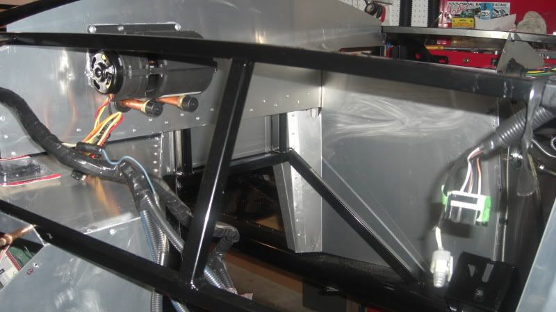
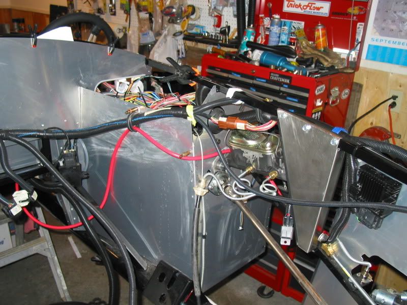
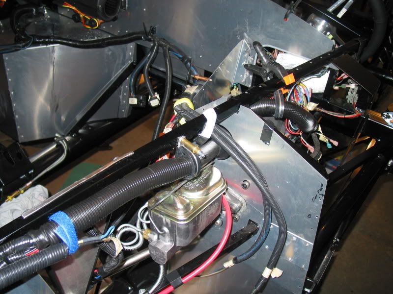
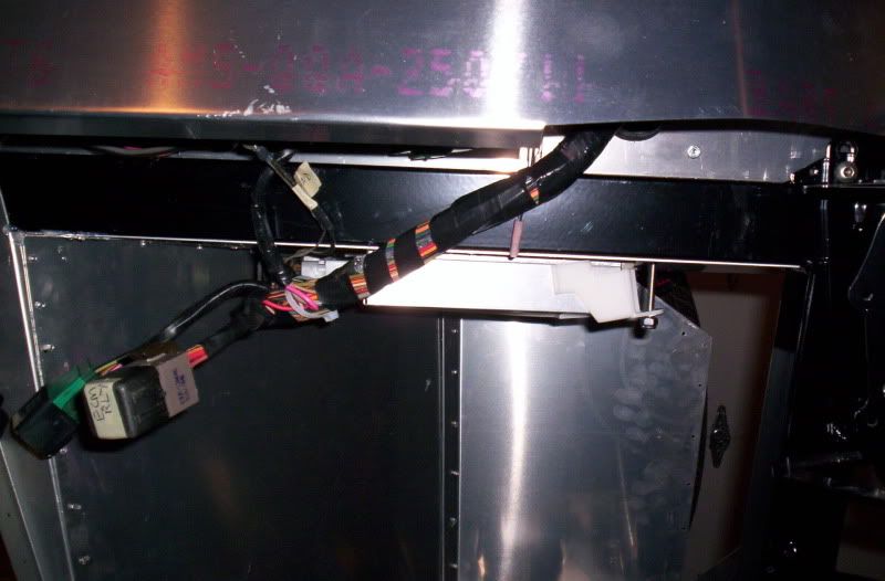
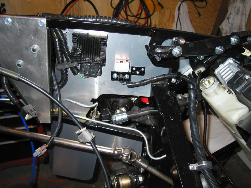
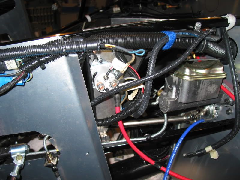
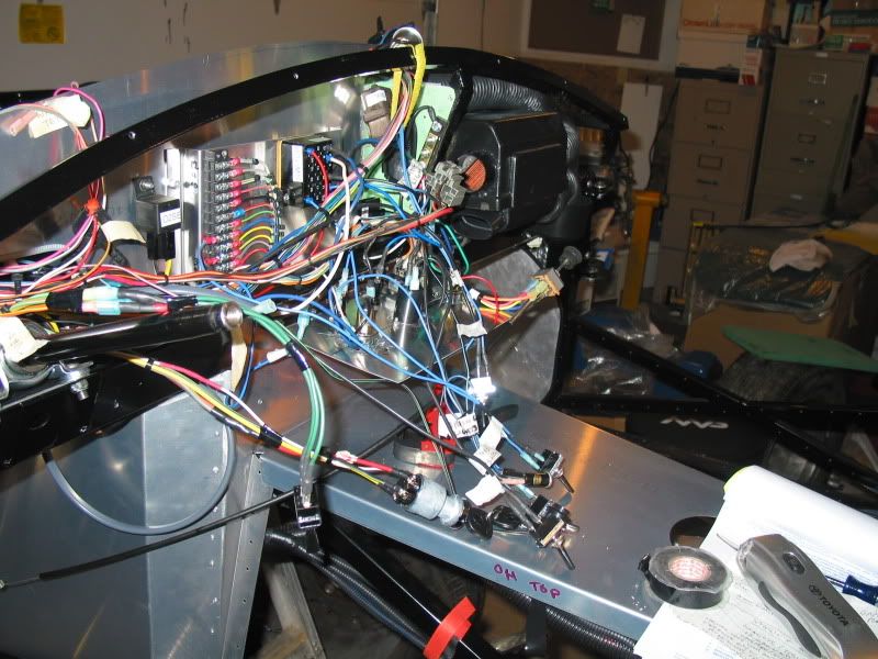
This photo shows the harness tentatively attached to the firewall. You can see the connectors for the salt and pepper shakers, the BAP sensor will be mounted to the right of them. (Picture's right side) Also visible is the section of harness that has the distributor connectors. I think I will run this along under the drivers side of the intake plenum. I can't remember how it was mounted on the Mustang..The red cable is the positive batery cable that leads up through the tranny tunnel from the trunk mounted battery. I hate having such a long run as the voltage may drop due to resistance, but this is the what the manual calls for.
I'm still undecided as to the mounting location of that battery cable. I may run it along the side of the frame, and then straight up to the starter solenoid. This would clean up the engine bay a bit. You can see the DRL module now mounted, and the stainless steel panel I made to mount a few other things such as the remote solenoid, fan relay, and possibly the distributor coil. It is hell drilling that stainless material, even with titanium drill bits. The harness that runs past the panel and the DRL is the coil connector. (I can see that it is time to change my Lordco Calender lol, still on September from last year..)
More wiring coming from the fuse box which is mounted under the steering column. You can see one of the large harness holders held in place for the time being with a Cleco, Ohter wires in this area are ground, and +12V wires that will attach to the starter solenoid's hot pin.
ECM Mounting This is where I have relocated the ECM now, on the side, rather than on the underside of the footbox.
This was the manuals suggested location, and where I first installed it. You can see that big wire harness that would be hanging below the dash. I wanted to avoid that.
COCKPIT INSULATION
It was quite common, even for the original Cobras to get pretty warm in the cockpit footbox areas. Being that there is only a thin layer of aluminum between your feet and the engine compartment, this stands to reason.
There are several solutions to help this problem. Some builders apply a second layer of aluminum to the engine side front of the footbox,spaced off it slightly to provide a dead air space in between. This acts somewhat as an insulation, as well as an added road debris deflector. I am planning on adding this to the front and underside of the drivers footbox. (This will also protect my rear brake line from header heat)
Some builders use a commercially available product such as Thermotec, that has a heat reflective surface, and in some cases is self adhesive, and apply this to the entire engine side of the footbox's. This seems to work quite well, but does look a bit odd when the hood is open. Certainly not the "original" look when done that way, although practical.
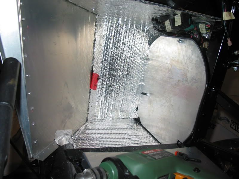
Others, including myself, decided to use insulating material on the inside of the cockpit. This is eventually covered by carpet, so it's not obvious. Products available that are popular are Dyna-mat, or Fat-mat, as well it's not uncommon to use spray/roll on liquid insulation, which has recently come available from Second Skin Products, called Firewall.
Some of these products can get a little pricey, so I am using another product that is equally effective, but less expensive. It is a double foil backed material that is often used for insulating hot water heaters, available at most building centres. On the floor only, I am adding an additional layer of Dyna-liner, as this area gets the most wear and tear, and will also act as a sound barrier from road gravel, and such kicked up by the tires.
The insulation is glued on, unless it's the self adhesive type. You can use spray adhesive such as 3M's Super 90 which has had good results. Measuring and cutting all the odd shapes is really half the battle. I can't see how it could be applied all at once, or it would be impossible to glue down tightly in all the little corners, etc. I also use special aluminum tape designed for high heat, to tape some seams where the material joins. This can help when laying the carpet, so seam edges don't get snagged, and lifted.
In addition to the footboxes, the upper firewall, and the back cockpit bulkhead can be insulated, more in the later case as a sound absorber from road noise.
With my luck the Wife will probably complain about cold feet..
This is a picture of the ECM protective kick panel I made from an aluminum serving tray, bought at the Sally Ann. It will eventually be covered in carpet. You can also see the beggining of the footbox insulation install.
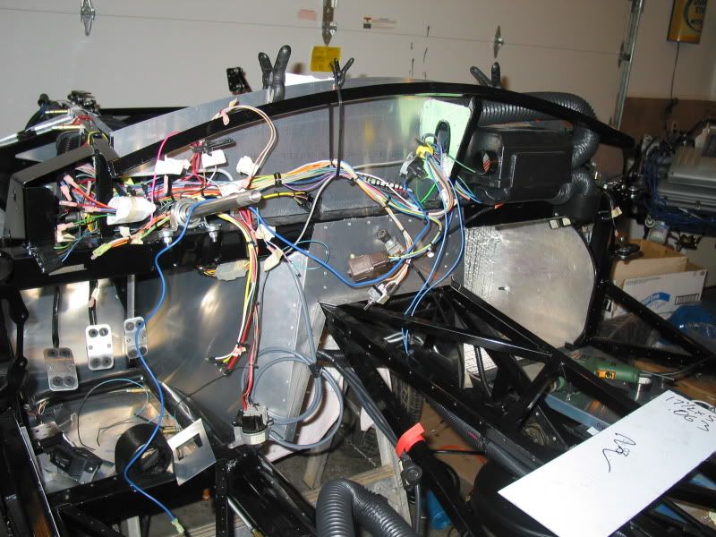
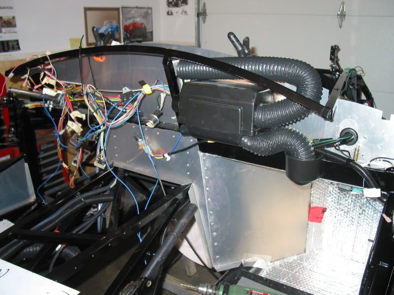
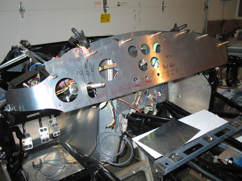
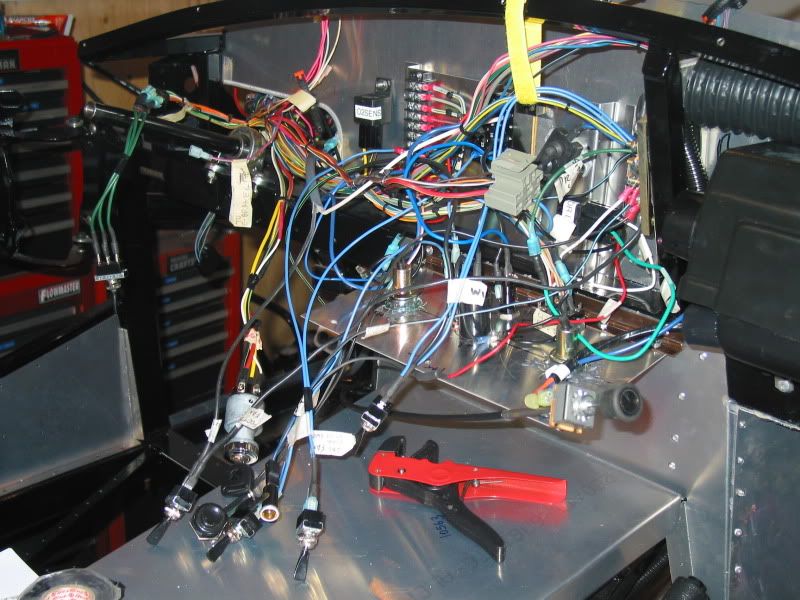
A view of the dash wire harness. There will be a lot more wire added to this area, as I install all the switches, and gauges.
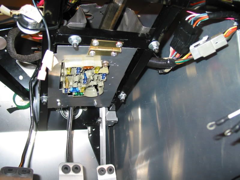
Fox Mustang fuse box installed in drivers footbox. I added a hinge so I can swing it down slightly for better access to the fuses.
Beginning to start on heater duct hose routing. There will be two more hoses on the drivers side for defrost and footbox heat. The hose, and the vent outlets comes complete with the optional heater. I installed some of the hoses now so I could decide on wire harness routing in the dash area, for the heater switch, and wiper switch, etc.
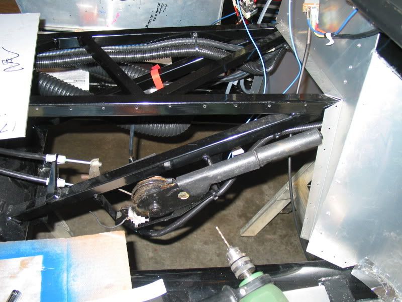
A view of the Fox Mustang e-brake handle installed. The kit frame comes with the bracket for it already welded and drilled for mounting this item. As well a black vinyl boot is included, to be installed after the carpeting is in. NOTE If anyone has a chrome, or aluminum billet handle that will fit the Fox e-brake, I'm looking for one..
A poor shot of the battery master switch installed (top of picture) This is the backside of it, showing the ground cable harness's attached. My idea is that once switched, all grounds will be cut off. I did run a seperate wire from the battery side of the switch, directly to the computer ground. This will allow the small current needed for the ECM to maintain it's memory. As mentioned previously the switch is mounted at the back of the tranny tunnel, for easy access from in the cockpit.
NOTE- PLEASE KEEP IN MIND THAT THIS BUILD THREAD WAS ORIGINALLY WRITTEN BACK IN 2009, AND I HAVE SIMPLY COPIED AND PASTED IT TO THIS FORUM FROM ANOTHER. THAT'S WHY SOME COMMENTS,SUCH AS THE ONE DIRECTLY BELOW THIS NOTE, ARE NOT CURRENT TO THIS YEAR..
As we had the warmest January on record here in southern BC, I have been busy trying to get a few yard/garden things done the last few weeks, which will hopefully give me more time now to work on the Cobra.
Time to add a few updates to the build progress.
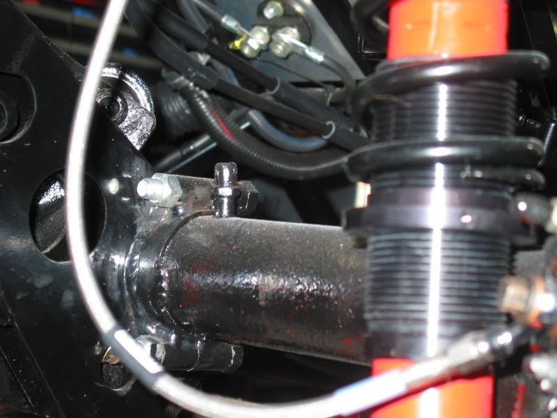
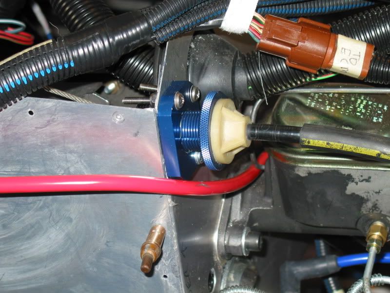
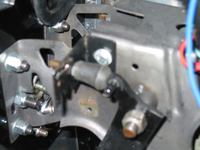
I have added an aftermarket clutch cable adjuster to the front of the foot box, as well as an aftermarket clutch cable quadrant. This replaces the stock Mustang self adjuster and clutch cable quadrant. Being the Mustang one's are all plastic, and 20 years old, I felt it had to go. I had to remove the pedal shaft anyway, to put new pedal bushings in. The clutch safety switch is also removed at this time. I have a neutral safety switch on the tranny, to prevent starting in gear..
In addition, getting rid of the this stock equipment allows more room in an already crowded area, above the pedal box, where a lot of wiring sits. Less chance of snagging a wire as well. I had to sand off some of the powder coat to slide the adjuster into place. I then had to drill holes in the front of the foot box to mount it. The adjuster comes with self tapping sheet metal screws, as they are intended to screw into a Mustang firewall. In my case there is a 1/4" steel plate behind my aluminum, so I used machine screws and nuts to hold it in place. I added a touch of white grease to the threads before the install, as the adjuster is aluminum, and the threads tend to be a tad sticky.
The new cable quadrant, is a simple addition to the clutch pedal shaft and replaces the Mustang plastic one. In this picture you can also see the back of the adjuster, as well how I have used zap straps to hold wiring harness in place, to stay clear of the quadrant.
I spent some time making a clutch pedal adjustable stopper. This allows you to set the pedal height. I can now have the pedal somewhat even with the brake pedal.
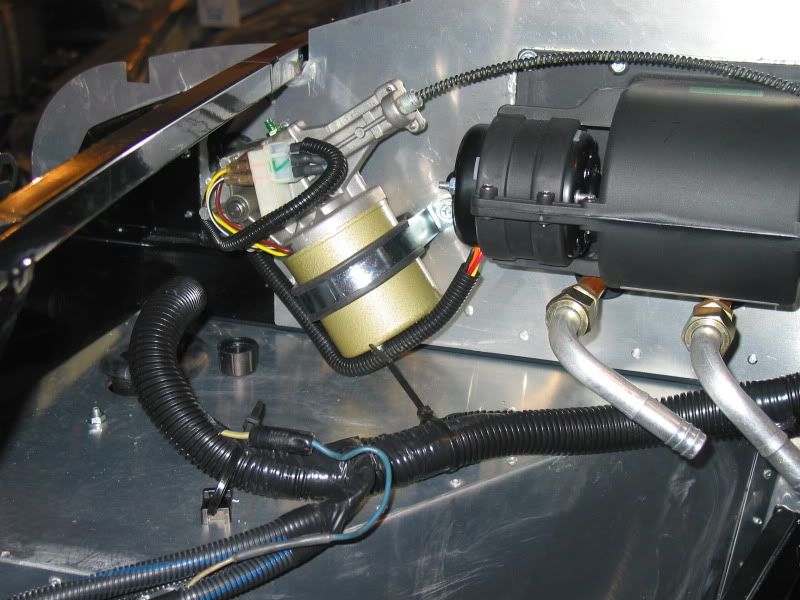
The Mustang used a cooling fan bolted to the water pump pulley. As mentioned previously the kit includes an electric fan. FFR has you controlling this fan by a manual dash toggle switch. I didn't really want to rely on having to keep one eye on the water temp gauge, and being there are inexpensive aftermarket thermo switches available, decided to add one. I bought the Flex-a-lite adjustable control switch. This lets me set the temperature's as to when the fan will turn on/off. I liked the idea of having a dash manual override switch as well. This could be useful if the controller was ever to fail, or if I was sitting in traffic, and I didn't want the fan continuously switching on and off. The control switch uses a probe which is inserted into the rad fins, by the upper coolant hose. Wiring it with the overide switch tooka bit of figuring, but overall wasn't to hard, once I had it straight in my head. I mounted the control inside the engine bay, so I can easily reach it to adjust it.
You can see it here, mounted next to my Daytime running light module, on what is called the F panel aluminum.
I installed the remote starter solenoid to the outside of my engine bay, on the stainless steel panel I fabricated. Putting it here helps keep down the wiring clutter that would otherwise be visible in the engine bay. Several other wires lead to the solenoid as a source of +12V power, in addition to the starter lead.
AC Bill, awesome build. I always think it is easy to build one of these beasts, but really it's not. Your build story shows how much detail and though goes into every piece.
Great story and I bet a lot of self satisfaction having done this project.
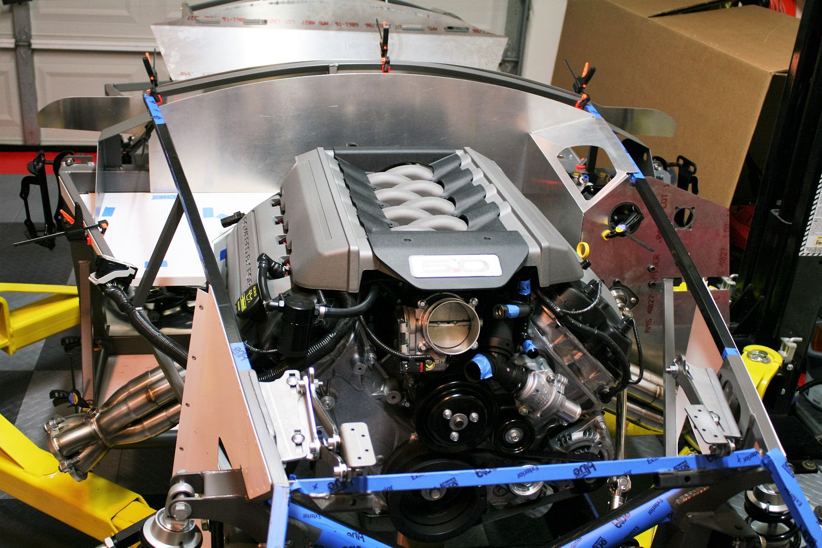
Since your build are there any new developments in engine options beyond the 4.6. I thinking Coyote 5.0. Likely has the same issues with the width of the cyl heads.
Factory Five Racing has done some refinements to allow for the Coyote motor being used. I guess they realize that the 4.6 engines will be only around for so long, and they needed to make the changes needed as Ford produced the newer engines..There are some challenges, such as mounting the alternator on a custom bracket, that sits down lower on the engine. For a 302 those massive cylinder heads make for a fairly tight squeeze. Reaching the rear header bolts can be quite interesting apparently. The "drive by wire" aspect of the Coyote means more electronics then ever, and they are limited in their mounting positions when using the donor wire harness. As more builders choose to use the Coyote, they will probably be the best ones to look for modifications, and further refinements. The issues will be approached similar as to how they were approached with the 4.6 when it first started being used. The builders forum will be a tremendous resource for new builders.
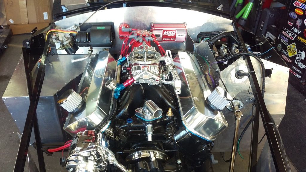
As a comparison, this is a 454 Chevy one builder chose to use. As you know they are huge, but here it looks no bigger then the Coyote.
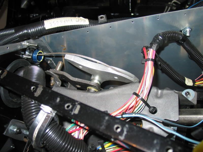
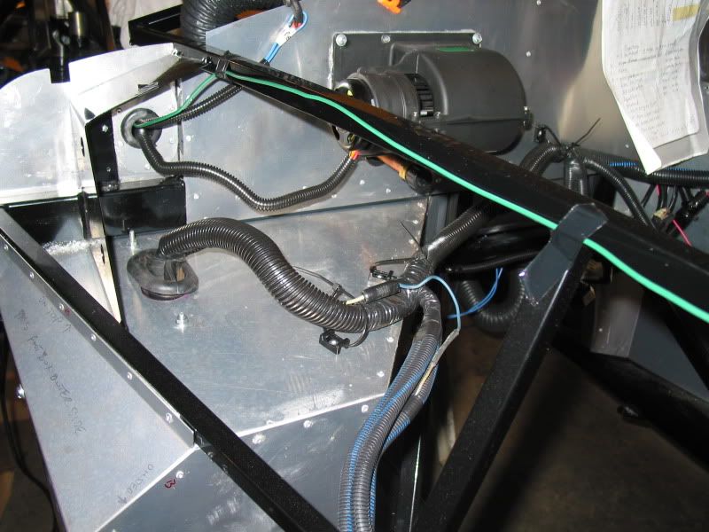
Still on wiring, I ran the wires (blue) for the windshield wiper motor to the firewall from the dash area, where the switch will be mounted. I also decided it would be a good time to run a wire (green) from the dash area, for a set of driving lights to be added later. Better to do it now while things are more easily accessed, then after the body is on. I will mount and wire a relay for these, and cover the wire with split loom harness cover.
I also covered the exposed heater fan motor wires in split loom cover to tidy things up, as well as protect them. One of the little things you learn on the build forums for example is, loosening the heater fan motor, and turning it, so that when re-mounted the wires protruding from the bottom of it, rather than the top. The wires are less obtrusive doing this. Not a big thing, but all these little bits you learn add up to a nicer built in the end. It's these things you learn from others experience, and not from the build manual.
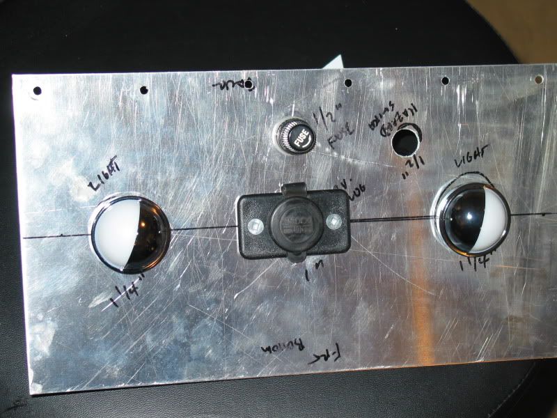
I have laid out the dash switch arrangment, and indicator light positions. You have to watch where these go, so you don't find out later, that they interfere with the dash mounting, or any gauge mounting. I am using the Lucas style toggle switches, in keping with tradition. They require a 1/2" hole to be drilled in the dash aluminum to mount them. I have several of these switches, in addition to the headlight, hazard, heater, turn signal, and dash light dimmer switches.
I also have indicator lights for the turn signals, high beam, alternator charging. I decided to skip the "check engine" idiot light as the Mustang has. I have gauges to let me know if there is a problem. I also planned to have reminder lights for when I have the cooling fan manual switch turned on, as well as a reminder for driving lights, as they will not be hooked up to my high beam switch and indicator light.
I then lined up and fastened the dash to the support frame, and double checked the position of everything. At the top of the dash you can see the clecos holding it in position, At these points I will tap the frame support to accept 8x32 machine screws, which will hold the dash in place once it has been upholstered. I will use finishing washers under the screw heads, to prevent them pulling thru the dash cover material. This also prevents the material from trying to turn as you tighten the screws. To support/stiffen, the lower part of the dash, you can use the small aluminum panels included in the kit, or fabricate your own to suit. As I will have underdash foot box courtesy lights I will make my own. These horizontally mounted support panels will also serve as a mounting point for my 12V electical outlet plug, (cell phone charger, etc) as well as my 4 way hazard switch. Some builders use "piano hinges" on these underdash panels, so you can simply unscrew the upper dash screws, and then swing the dash out and down. This is great if you need access to the back of the dash. I plan on using them. You can see how the dash curves back on either side to be also secured to a frame member. At these points I used a "L" brace screwed to the frame, and will run two screws into the dash aluminum..
Next I pull the dash off, drill the needed holes for switches, and indicator lights. I then glue the padded dash material, (supplied in the kit) to the aluminum, then let it dry before final install of the gauges, lights, and switches. Then I have to wire it all..that should be fun..or not..
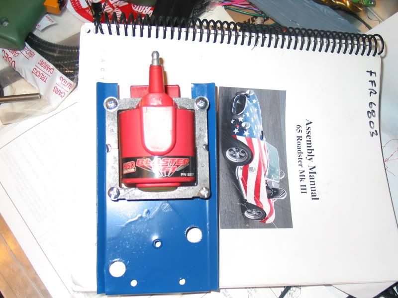
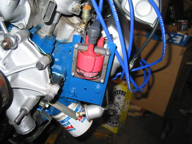
I decided to fabricate a mounting bracket for my ignition coil. Partly as I couldn't figure out how to make use of the original Mustang coil bracket. The one from the 90 GT is an odd shaped thing, with several angles. The FFR manual calls for you mounting the coil on the left side of the engine compartment, similar to the Mustang arrangement. I have seen where some builders opted to mount their coil closer to the distributor, on the engine. My Taylor plug lead set came with two coil leads, one long and one short. Perfect, I can use the short one.
So I found a piece of metal, kicking around in "stuff that you keep, as you may use one day" box, that looked perfect. I cut it with my angle grinder with cutting wheel, and drilled the coil mounting holes, after first lining up the coil on it. I couldn't use the screws from the Mustang bracket, so I had to dig around and find some machine screws and nuts to hold the coil to the new bracket.
I then had to mark and drill holes where the two bolts would hold it to the block. A coat of engine enamel to match the block, and it was ready to mount. Bracket.
I had some no longer used holes, at the left front of the block, where the AC compressor, and power steering brackets used to mount. These were perfect for mounting the coil bracket. I used some aluminum collars on the mounting bolts, to space the coil out from the block aways. This gives it a bit of air space, so I hope it will not overheat, and malfunction. Mounted to block.
NOTE I hope you have a good assortment of nuts, bolts, machine screws, washers, etc., etc., that you have collected over the years, if you start one of these projects. I have been fairly lucky in that I inherited a fine collection of odd ball stuff from my Dad, as well I have been hoarding any little items as listed as I came across them over the years. This has saved me from numerous trips to the hardware store, although at times I still need a certain size, I need to run out for..
Patience unfortunately is required when building a car capable of 130+mph. Rush something and you may end up in a ditch upside down.
I would love to have it finished and be cruising. Funny thing is, many owners say that the build itself is something they really miss doing. Many have started a second car because of that.
A couple of things I have been working on the last few days.
I decided to make an underdash panel. This actually stiffens up the dash, and supports it at the bottom edge. I used a piece of aluminum of about the same gauge as the kit aluminum (.040), and added footbox lights, a 12 volt outlet, and fuse for it, for charging cameras, cell phones etc. As well I drilled a hole for the hazard (4-way flashers) switch to mount to. I will mount this in the lower center of the dash, above the tranny tunnel. Unless you lean over and look up at it, it should be mostly out of site, I am undecided if I should glue some interior vinyl to it similar to the dash material, or perhaps some carpeting, to match the floor. UNDERDASH PANEL
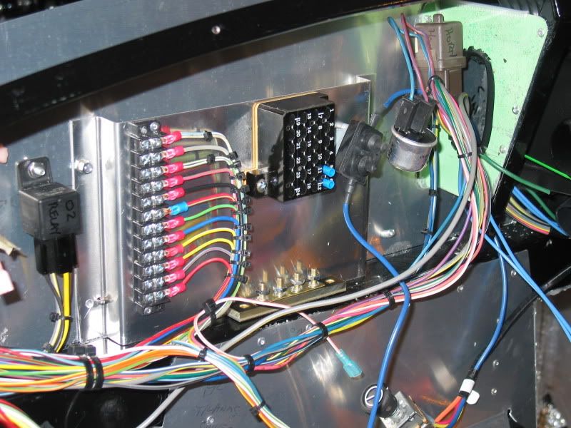
The FFR manual has you mounting many things behind the dash, mostly to the backside of the firewall. Items such as relays, and wire terminal strips, etc. I didn't want my engine side of the firewall to look cluttered up, with all the rivets and screw fasteners for these items, protruding through from the inside. I decided to make a stand off plate to mount some of these items to, instead. I didn't have a sheet metal brake tool, but some careful hand bending using a vice, worked good. Again aluminum was used. This addition really stiffens up the firewall I found, so that was an added bonus. Here you can see my wire terminal strip, of which many of the dash switches will be wired to. As well, I added a second power terminal to run accessories off of, things like driving lights, footbox cooling fan, etc. I also attached the heater circuit breaker. I still have to attach my ground terminal strip, (visible at the base of the stand of plate), to which switch, and other grounds will be attached. Also visible is the Horn relay (brown), 02 relay, (black). I am still thinking on how to attach the hazard relay (cylindrical), so that I can prevent it from flopping around, but still keep it easily removable in case I need to change it in the future. Perhaps a simple zap strap will suffice. Once all my wiring of switch's and gauges, etc. is in place, I will bundle and securely fasten the harness. STAND OFF PLATE
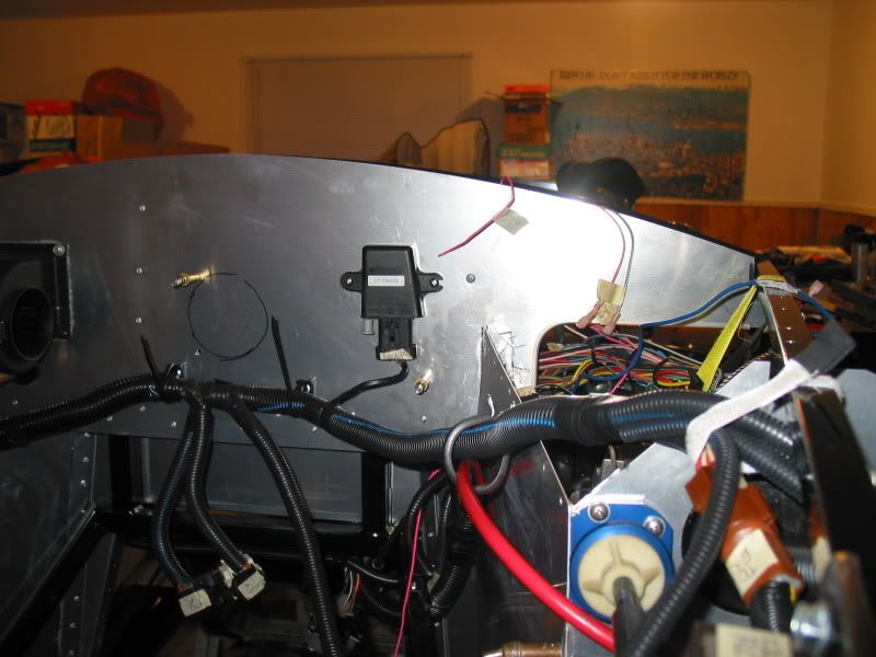
I used one of the holes drilled in the firewall needed to mount the stand off plate, to also mount the BAP sensor. I hope it will be in the correct position once the engine is in, and wired. That's always a problem in building these cars. You really have to really think things out prior to fastening something permanently, or you may just end up having to start all over again. As you can see I still need to finish fastening other sections of harness in the engine compartment. BAP SENSOR
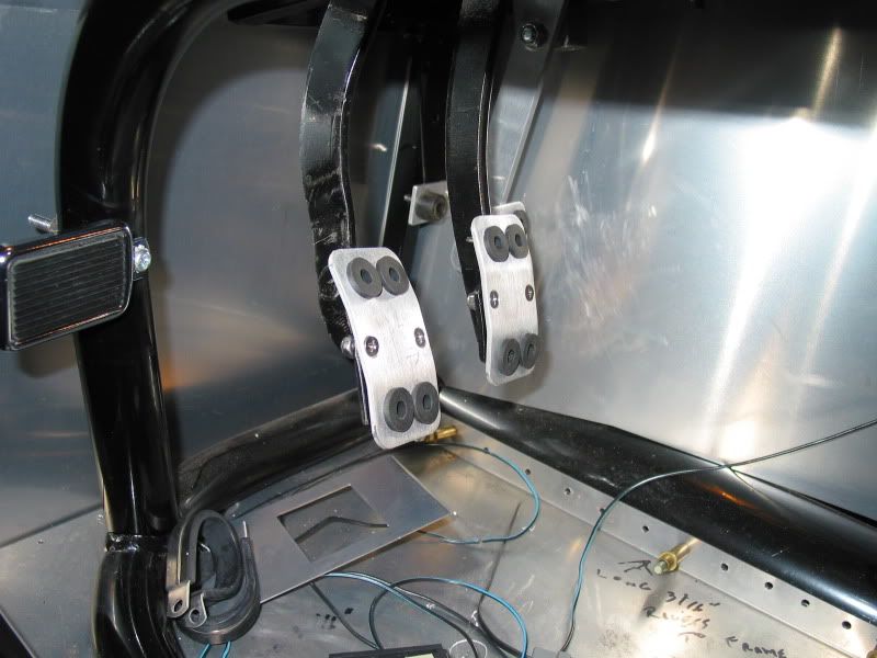
I had alluded to a small modification I made earlier in this thread, and now have some pictures. You need to make something to control the clutch pedal height, so it is somewhat even with the brake pedal. This is for looks, as well as driver practical foot positioning. Here you can see, (although a tad blurry)my clutch pedal stop. It is adjustable so I can raise and lower the pedal to suit. I mounted a brace for it to the pedal box, and it has a rubber cushion for the back of the pedal arm to strike, when the clutch is released. In this case I set it to hit the small arm that was used for the original Mustang cable adjuster, and safety switch. This prevents a clunk every time it's released, as well as any rattling when driving. I can adjust the clutch cable using the firewall adjuster, to set the cable correctly. CLUTCH PEDAL STOP
I also needed to make a gas pedal stop. This prevents the over extending of the FFR throttle cable, which is provided in the kit, to replace the stock Mustang cable. If using the stock Mustang gas pedal, and arm, the bracket welded on the frame already acts as a stop. In my case, I am using a Russ Thompson custom made pedal, (barely visible) specially designed for these cars. The advantage of this aftermarket pedal set up, is that you get smoother control of the throttle. There have been many complaints from builders that used the Mustang pedal set up, who say it has an on/off type feel to it. Very touchy.. I added a rubber cushion to this stop as well, for those wide open throttle moments, again so it doesn't clunk against metal. It is also adjustable.
Also visible in this picture is my little homemade dead pedal. This is for the left foot to rest while crusing, and off the clutch. It can also help support you when bracing for high G cornering.. GAS PEDAL STOP
In addition to these items, I also finished wiring up my adjustable thermo control for the cooling fan. I'm not great at wiring, but I think I have all it figured out. I hope...lol
I made some more progress, although this is the slowest part of the build so far, and certainly not my favorite part.
There are a couple of ways of doing this dashboard wiring. One is to fit all the switches, indicator lights, and gauges into the raw dash, and then running all the needed wires to them, one by one. Some builders do this before applying the supplied dash material to the aluminum. This requires you to pull all the switches, lights, and gauges back out, then to re-install them again after the dash is covered. This seemed like additional time consuming work to me.
I thought why not just use the bare dash panel to gauge the length of wires needed to reach everything, run the wires to the switches, etc. and then cover the dash before doing the final install. The indicator lights and the gauges can't be wired in till after it's covered, as they install from the front. No reason I can't have all the wires in place prior to that. The switches install from the back so I can actually hook them up at this point. First I had to decide on the location of the holes needed to be drilled for the switches, and indicator lights. Once I had that figured out, I used a multi-step drill bit, (or Unibit as they are sometimes called), to drill the holes to the correct size. What a great tool this is, and well worth the few dollars. FFR already have the gauge holes, ignition switch, and horn switch holes lazer cut into the aluminum.
SWITCH WIRING
I have the following switches now all wired up, ready to fasten to the dash. Ignition, horn, radiator fan override switch, wipers, driving lights, heater, foot box cooling fan, dash dimmer, headlight, and turn signal.
I have started in on the indicator light wiring as well, so the connectors will just have to be attached to them. I have the following indicator lights. L & R turn signal, high beam, alternator charge, e-brake, driving light, and rad fan override. (The rad fan override light will remind me that I have the fan turned on manually, as I doubt I would hear it over the side pipe exhaust noise)..
The next step will be to glue the dash cover on, which as I mentioned is supplied from FFR. It is a black, thin padded vinyl material, already cut to shape. You still need to cut out the holes in it once glued on, for the gauges, indicator lights, and switches. The material is slightly over sized so that you can wrap it around behind the dash aluminum for added bonding. Glue choices are builders choice. Some use the 3-M spray adhesives, #90, or #88 are popular choices. Weldbond Contact is supposed to be good, this is a brush on, so may be a tad tidier then the spray adhesives. The main thing you have to be careful about is that you don't choose a glue that will chemically react with the vinyl, and cause it to disintegrate. You also need to prep the aluminum prior to gluing. Rough up the aluminum surface, with a scotch pad, or sandpaper, then carefully wipe it down with acetone or lacquer thinner. I'll post pictures of it when I get to it.
I also installed the wiper motor to the firewall. The band bracket that comes with the it is to large to hold the motor firmly, so I made a small bracket for the back of the motor, which stands it off the firewall slightly. This way the band bracket tightens up just fine. WIPER MOTOR INSTALLED.
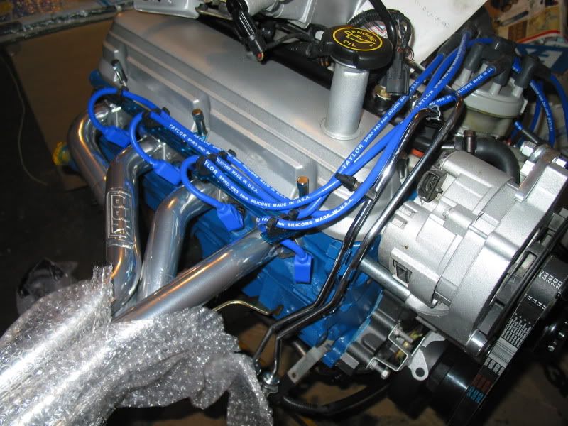
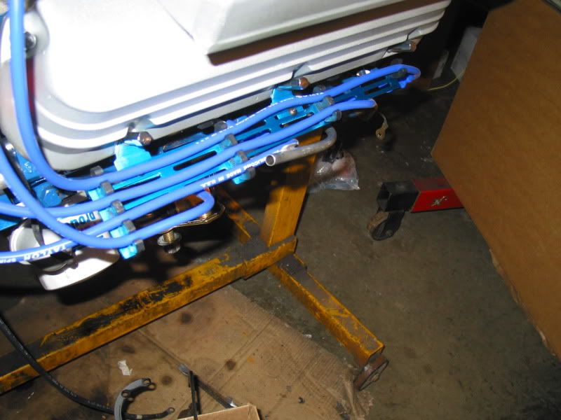
I also mounted the plug wire holders to the engine. They are a blue anodized aluminum brace that fits to the valve cover bolts, made by MR. Gasket. They seem to hold the plug wires clear of the headers, which was my main concern, as I have read of builders having them melt from the heat. The angle of the plug boots can also be a factor in this problem, so choose the correct ones. I had one fellow tell me that he had a problem with the plastic holders on a similar system actually melt on him. I hope that this doesn't happen! SPARK PLUG WIRE HOLDERS